Fan containment systems with improved impact structures

Inactive Publication Date: 2012-04-26
HONEYWELL INT INC
View PDF15 Cites 22 Cited by
  • Summary
  • Abstract
  • Description
  • Claims
  • Application Information

AI Technical Summary

Problems solved by technology

However, the fan casing is usually fabricated from a metallic material, and increasing the thickness of the casing, adding additional stru

Method used


Image

  • Fan containment systems with improved impact structures
  • Fan containment systems with improved impact structures
  • Fan containment systems with improved impact structures

Examples


Embodiment Construction

[0012]The following detailed description is merely exemplary in nature and is not intended to limit the invention or the application and uses of the invention. Furthermore, there is no intention to be bound by any theory presented in the preceding background or the following detailed description.

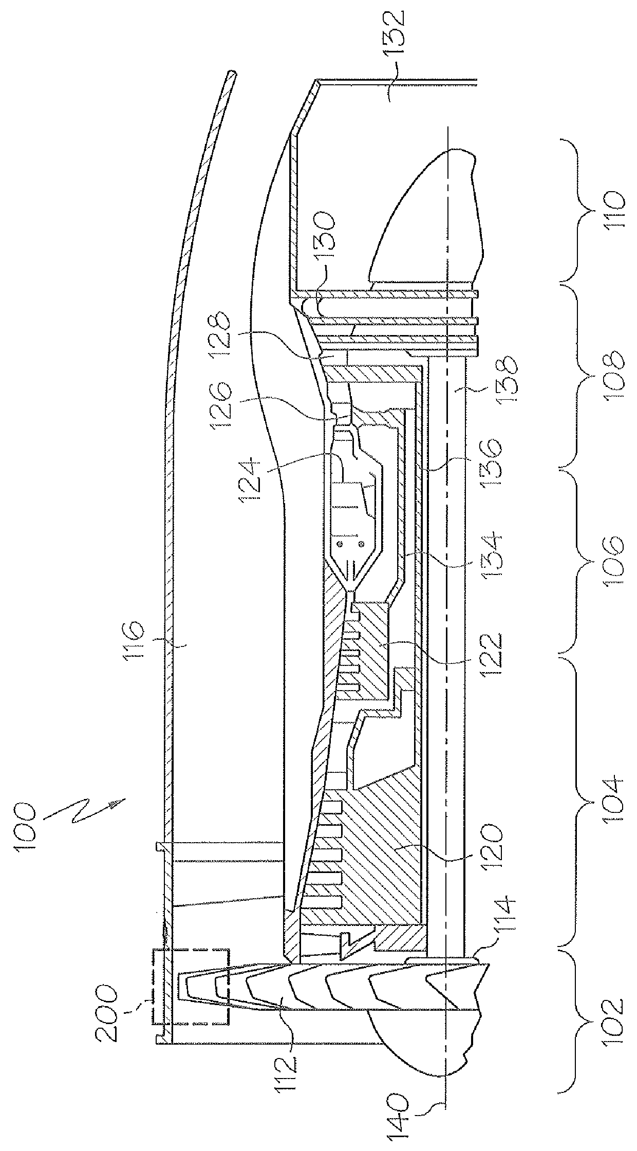
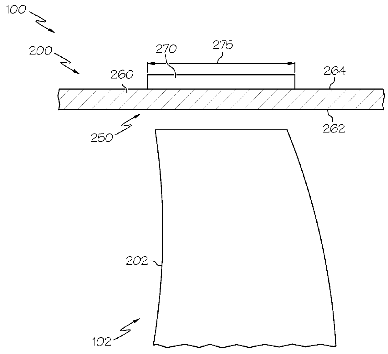
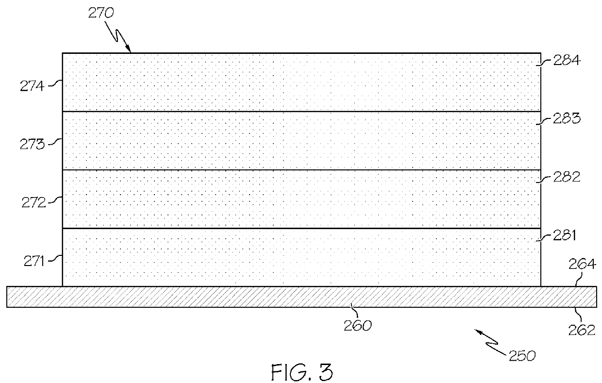
[0013]Broadly, exemplary embodiments discussed herein provide improved fan containment systems for gas turbine engines. An exemplary fan containment system includes a casing that surrounds the fan section of the engine and an impact structure mounted on an exterior or outer surface of the casing. The impact structure is made up of a number of material layers impregnated with a shear thickening fluid for improving impact absorption.

[0014]FIG. 1 is a partial, cross-sectional view of a gas turbine engine 100 in accordance with an exemplary embodiment with the remaining portion of the gas turbine engine 100 being axi-symmetric about a longitudinal axis 140. In the depicted embodiment, the gas tu...


PUM

PropertyMeasurementUnit
Viscosityaaaaaaaaaa

Abstract

Methods and apparatus are provided for a fan containment system for a gas turbine engine having a plurality of fan blades includes a cylindrical casing with an inner surface surrounding the plurality of fan blades and an opposing outer surface; a first layer of fabric material positioned on the exterior surface of the cylindrical casing; and a shear thickening fluid impregnated within the first layer of fabric material.

Description

TECHNICAL FIELD[0001]The present invention generally relates to fan containment systems in gas turbine engines, and more particularly relates to fan containment systems in gas turbine engines with improved impact structures.BACKGROUND[0002]A gas turbine engine is used to power various types of vehicles and systems. A particular type of gas turbine engine that may be used to power aircraft is a turbofan gas turbine engine. A turbofan gas turbine engine may include, for example, five major sections: a fan section, a compressor section, a combustor section, a turbine section, and an exhaust section.[0003]The fan section is positioned at the inlet section of the engine and includes a fan that induces air from the surrounding environment into the engine and accelerates a fraction of this air toward the compressor section. The compressor section raises the pressure of the air it receives from the fan section and directs a majority of the high pressure air into the combustor section. In th...

Claims


Application Information

Patent Timeline
IPC IPC(8): F04D29/40B23P17/00
CPCF01D21/045Y10T29/49229F05D2300/603
Inventor MICKELSEN, JUSTIN C.DODDMAN, WILLIAM H.WATSON, BILL
Owner HONEYWELL INT INC
Why Eureka
Try Eureka