
Printable facial mask and printable facial mask system with enhanced peripheral visibility

a facial mask and printer technology, applied in the field of facial masks, can solve the problems of reducing the size of the eye hole, limiting the vision field of the wearer, and observing being unable to recognize an otherwise well known character or person, so as to achieve maximum visibility, reduce the effect of the aesthetic appearance of the image, and facilitate the wearer to see through the mask

Inactive Publication Date: 2012-05-03
RODRIGUEZ LUIS JOAQUIN
View PDF16 Cites 3 Cited by
  • Summary
  • Abstract
  • Description
  • Claims
  • Application Information

AI Technical Summary

Benefits of technology

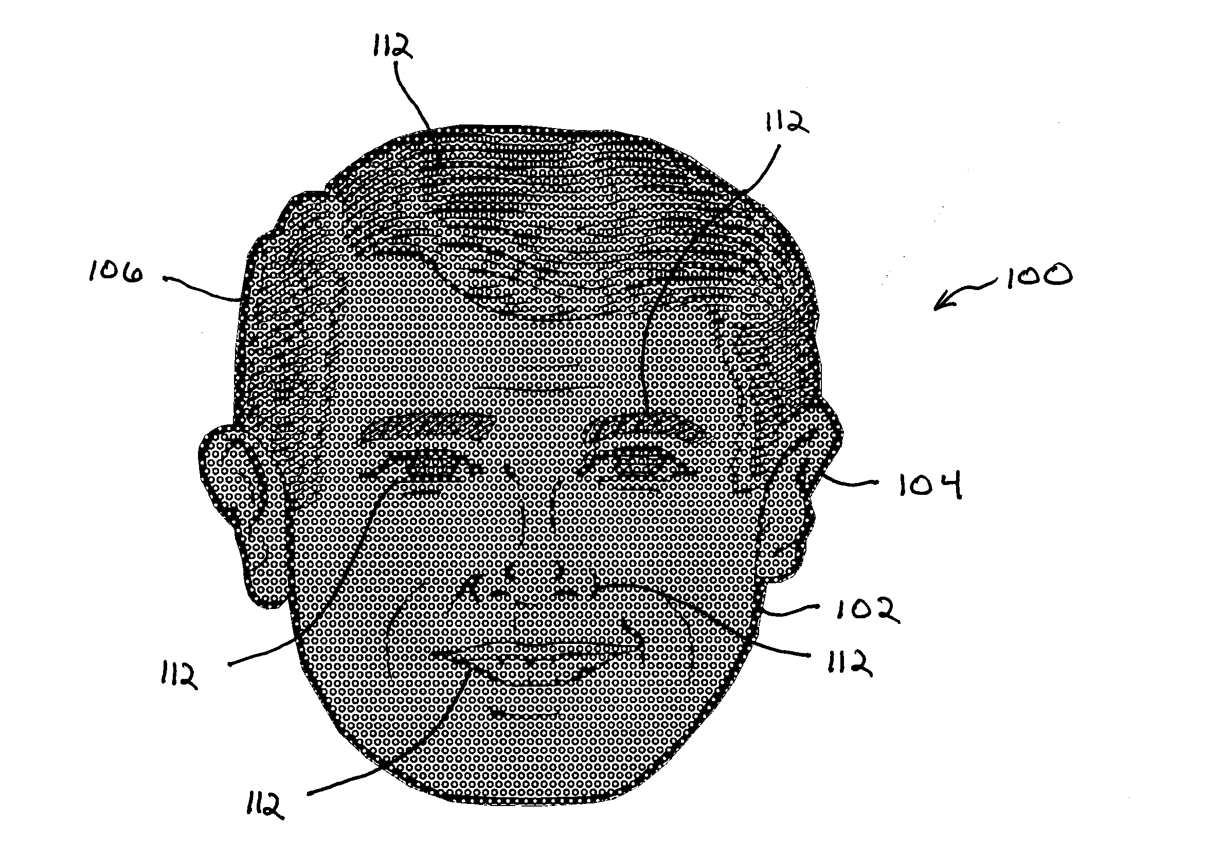
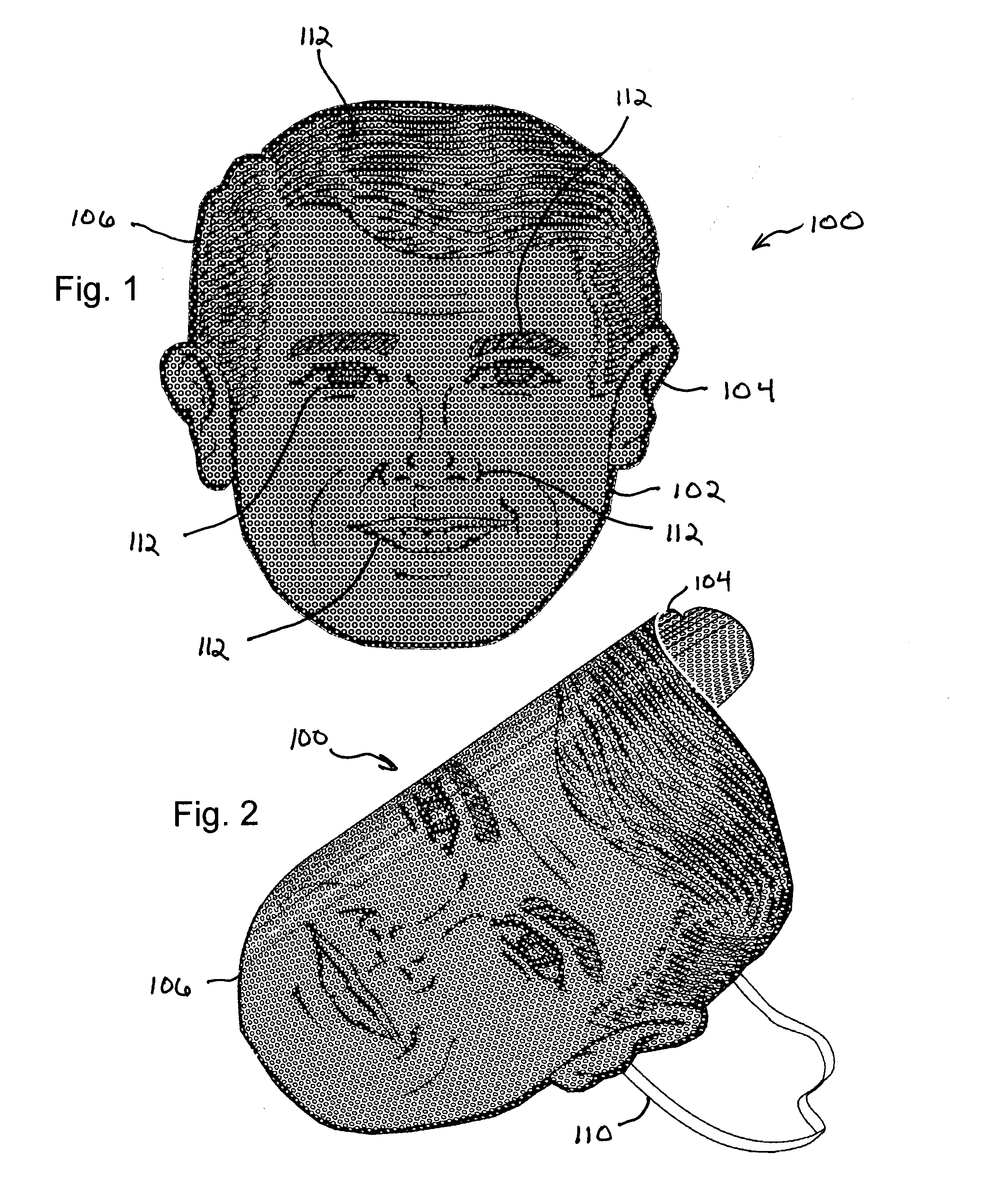
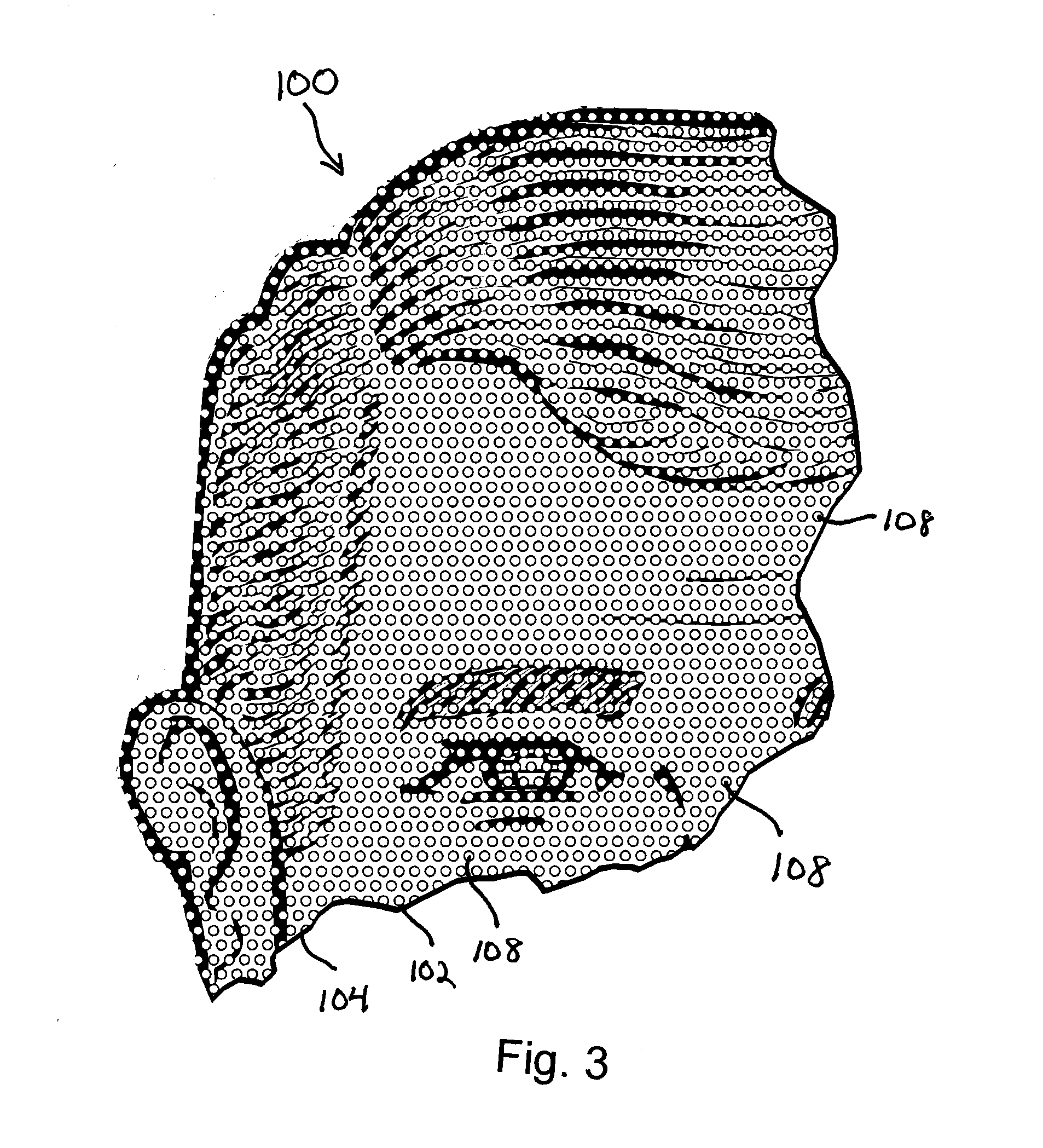
[0007]A facial mask according to the present invention generally comprises a facial mask printed on a transparent substrate such that the image comprises a patterned plurality of transparent spots or orifices allowing the user to see through the printed image. The pattern of transparent spots or orifices can be sized and spaced to minimize the effect on the aesthetic appearance of the image while providing a user with the maximum visibility. For example, a plurality of relatively small transparent spots or orifices can be arranged in a relatively dense pattern. The high density of spots allows the wearer to easily see through the mask while the small size of the spots prevents distortion of the image from the perspective of an observer when viewed at a distance. Furthermore, the pattern allows a detailed predetermined image to be applied to the facial mask with minimal distortion by eye holes or large perforations.
[0011]In another aspect of the present disclosure, various disclosed methods of forming a facial mask can be utilized in forming portions of a conventional facial mask or facial accessory. For instance, a conventional facial mask can include one or more eye portions, wherein said eye portions are formed with the disclosed methods of the present invention such that the eye portions include a printed image and a plurality of void spaces so as to provide visibility to a wearer while improving the overall appearance of the facial mask to an observer by removing the traditional eye openings of a conventional mask. Alternatively, a facial accessory such as, for example, glasses can include a lens portion formed with the disclosed methods of the present invention having a printed image with a plurality of void spaces to provide visibility to the wearer while depicting a desired printed image to observers.

Problems solved by technology

While eye holes are necessary for both convenience and safety, the appearance of eye holes often detract from the overall aesthetic appearance of the mask and may result in observers being unable to recognize an otherwise well known character or person.
Unfortunately, decreasing the size of the eye holes has the added drawback of limiting the field of vision of the wearer by essentially creating a tunnel vision effect.
In particular, the wearer's peripheral vision is often sacrificed creating a safety risk and general discomfort for the wearer.
One drawback to this approach is that the stretchable openings requires that the entire mask to be constructed of a flexible and stretchable material that can make printing of the desired face or image on the mask difficult.
Similarly, as the flexible and stretchable material contours to the wearer's face, the printed face or image can become deformed or distorted when contoured over different wearers' faces.
While these approaches eliminate the need to cut eyeholes into a mask, these approaches again suffer from the potential of the woven or knit material distorting on a user's face making them unrecognizable.
Unfortunately, current mask designs face a tradeoff between image quality from the point of observers and vision quality from the perspective of wearer's of these masks.

Method used


Image

  • Printable facial mask and printable facial mask system with enhanced peripheral visibility
  • Printable facial mask and printable facial mask system with enhanced peripheral visibility
  • Printable facial mask and printable facial mask system with enhanced peripheral visibility

Examples


Embodiment Construction

[0038]As illustrated in FIGS. 1 and 2, a representative facial mask 100 of the present invention can comprise a printed image 102 that is directly printed onto a flexible sheet 104. Flexible sheet 104 can comprise a perimeter 106 that substantially matches and defines the exterior boundaries of the printed image 102. As best seen in FIG. 3, facial mask 100 generally includes a plurality of void spaces 108 that are typically evenly spaced and small in overall size. In one representative embodiment, void spaces 108 can occupy from about 30% to about 50% of the area of flexible sheet 104. Individual void spaces 108 are generally sized so at to be indistinguishable from the perspectives of both a wearer and an observer without close, focused observation. Generally, each individual void space can have a size of between about 1 mm to about 2 mm. In one representative embodiment, each void space 108 has a diameter of 1.5 mm. Void spaces 108 can comprise physical perforations within the fle...


PUM


Abstract

A facial mask and related methods of manufacture wherein the facial mask include an image printed on a flexible substrate. A plurality of individual void spaces are defined within a perimeter of the image. These void spaces can be defined by the intentional absence of ink left during the printing process or by individual perforations through the flexible substrate that allow a wearer of the facial mask to see through the printed image without obscuring the user's field of view including peripheral vision. The plurality of void spaces are generally sized and spaced so as to minimize their effect on the aesthetic appearance of the image to observers while providing a user with the maximum possible visibility. The disclosed methods of manufacture can be used with conventional masks or accessories so as to reduce the visual impact of eye and mouth openings that detract from their overall appearance.

Description

CROSS REFERENCE TO RELATED APPLICATIONS AND PRIORITY CLAIM[0001]This application claims the benefit of U.S. Provisional Application Ser. Nos. 61 / 407,096, filed Oct. 27, 2010 and entitled “TRICKSTICKMAXMASK,” and 61 / 483,793, filed May 9, 2011 and entitled “PRINTABLE FACIAL MASK AND PRINTABLE FACIAL MASK SYSTEM WITH ENHANCED PERIPHERAL VISIBILITY”, by the present inventor and both of which are hereby incorporated by reference herein. In addition, this application is related to U.S. Utility application Ser. No. 13 / 282,168, entitled “PRINTABLE FACIAL MASK AND PRINTABLE FACIAL MASK SYSTEM WITH ENHANCED PERIPHERAL VISIBILITY”, by the present inventor and filed concurrently with the present application and is hereby incorporated by reference.FIELD OF THE DISCLOSURE[0002]The present invention relates to a facial mask and related methods of manufacturing. More specifically, the present invention is directed to a facial mask providing enhanced visibility to a wearer while simultaneously displ...

Claims


Application Information

Patent Timeline
IPC IPC(8): A42B1/18
CPCA41G7/00
Inventor RODRIGUEZ, LUIS JOAQUIN
Owner RODRIGUEZ LUIS JOAQUIN
Learn More