Control valve

a control valve and valve body technology, applied in the direction of valve operating means/releasing devices, functional valve types, transportation and packaging, etc., can solve the problems of poor structure and potential safety hazards for hydraulic equipmen

Active Publication Date: 2012-05-03
CLOUD NETWORK TECH SINGAPORE PTE LTD +1
View PDF10 Cites 2 Cited by
  • Summary
  • Abstract
  • Description
  • Claims
  • Application Information

AI Technical Summary

Problems solved by technology

However, the commonly used control valve has a poor structure and is prone to switching between the two controls accidently, thereby generating a potential safety hazard to the hydraulic equipment.

Method used


Image

  • Control valve
  • Control valve
  • Control valve

Examples


Embodiment Construction

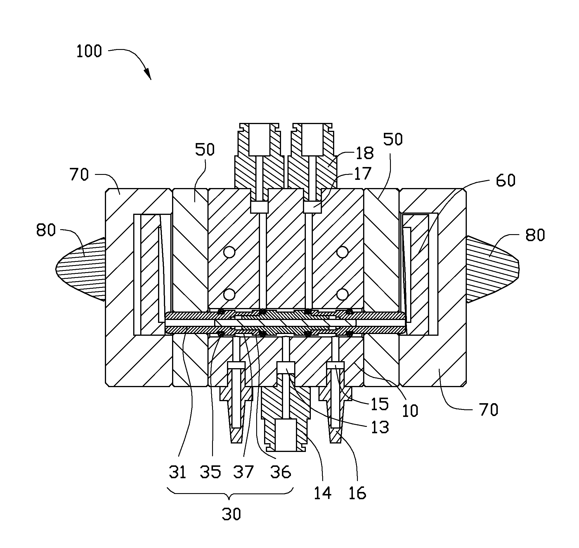
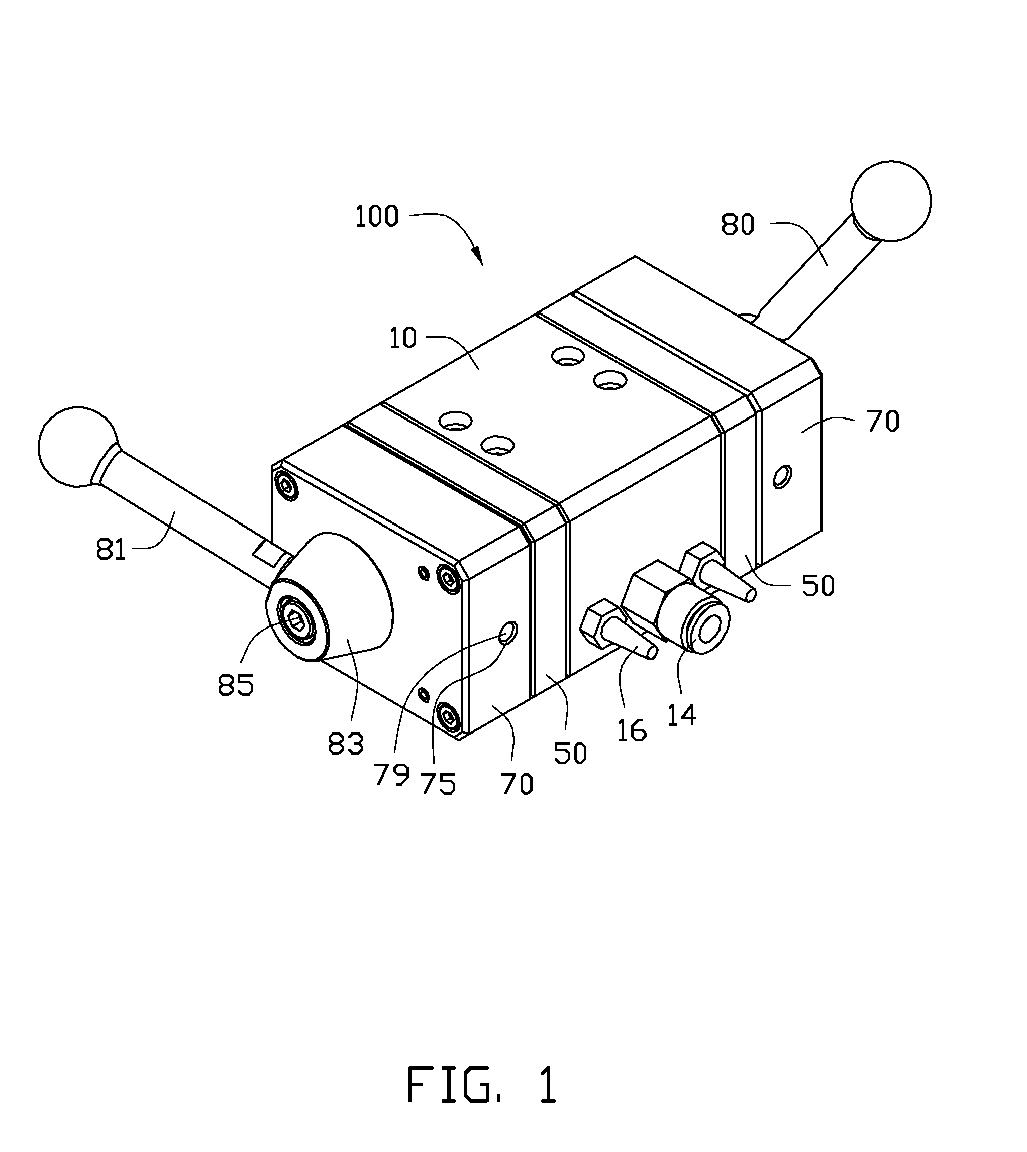
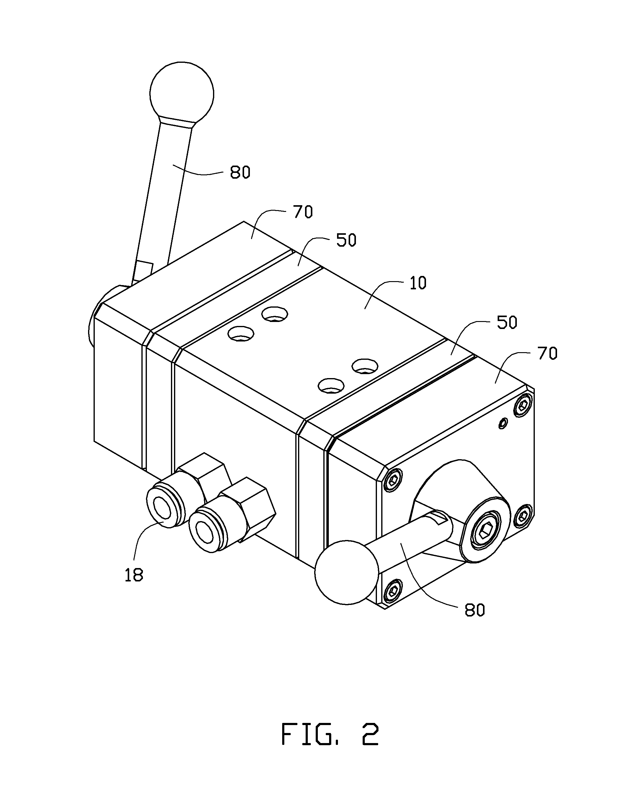
[0013]Referring to FIGS. 1 through 3, an embodiment of a control valve 100 includes a valve body 10, a valve plug 30, two clamping boards 50, two adjusting elements 60, two clamping covers 70, and two operating members 80. The valve body 10 is a hollow body. The valve plug 30 is movably or slidably assembled within the valve body 10. Two ends of the valve plug 30 are respectively exposed from two ends of the valve body 10. The two clamping boards 50 are respectively assembled to two ends of the valve body 10 and sleeved on two ends of the valve plug 30, thus, the valve body 10 is sandwiched between the two clamping boards 50. The two adjusting elements 60 together with the corresponding two clamping covers 70 are respectively mounted to the two clamping boards 50, and are adjustably assembled to two ends of the valve plug 30 for controlling the control valve 100 to switch between an open state and a closed state. The two operating members 80 are respectively assembled to the two cla...


PUM


Abstract

A control valve includes a valve body, a valve plug, two adjusting elements and two operating members. The valve body has a valve hole defined through the valve body and further defines an inlet hole and two outlet holes respectively communicating with the valve hole. The valve plug is movably assembled within the valve body. Two ends of the valve plug are respectively exposed to the outside of the valve body. The two adjusting elements are respectively mounted to two ends of the valve body and respectively adjustably resist against two ends of the valve plug. The two operating members are respectively fixed to the two adjusting elements for driving the two adjusting elements to move the valve plug within the valve hole of the valve body, and thereby controlling the control valve to switch between an open state and a closed state.

Description

BACKGROUND[0001]1. Technical Field[0002]The present disclosure relates to control mechanisms, and particularly, to a control valve.[0003]2. Description of Related Art[0004]Control valves are widely applied in many fields such as hydraulic equipment, to control the flow of a liquid or gas. A commonly used control valve often includes two controls, which are switched during use, for controlling the supply to the hydraulic equipment. However, the commonly used control valve has a poor structure and is prone to switching between the two controls accidently, thereby generating a potential safety hazard to the hydraulic equipment.[0005]Therefore, there is room for improvement in the art.BRIEF DESCRIPTION OF THE DRAWINGS[0006]Many aspects of the disclosure can be better understood with reference to the following drawings. The components in the drawings are not necessarily drawn to scale, the emphasis instead being placed upon clearly illustrating the principles of the control valve. Moreov...

Claims


Application Information

Patent Timeline
Patent Type & Authority Applications(United States)
IPC IPC(8): F16K1/00
CPCF16K31/52483F16K11/07Y10T137/8671
Inventor XU, XIAO-BINGWEN, QING-SONG
Owner CLOUD NETWORK TECH SINGAPORE PTE LTD
Why Eureka
Try Eureka