Ocean wave energy converter and method of power generation

a converter and power generation technology, applied in the direction of electric generator control, machines/engines, mechanical equipment, etc., can solve the problems of increasing rpm, compromising torque, and building structures with the size of a building with many floors, and not as efficient in producing electricity

Inactive Publication Date: 2012-05-03
VASSILIOS VAMVAS
View PDF7 Cites 25 Cited by
  • Summary
  • Abstract
  • Description
  • Claims
  • Application Information

AI Technical Summary

Benefits of technology

[0014]A main feature of the embodiment described herein besides simplicit...

Problems solved by technology

Linear generators, though, are not as efficient in producing electricity compared to rotational ones.
The results have been the construction of structures with the size of a building with many floors that require large investments and which, are at a high risk since they operate submerged offshore.
However increasing rpm compromises torque.
It is the slow nature of the rise and fall of the waves resulting in slow mechanical...

Method used


Image

  • Ocean wave energy converter and method of power generation
  • Ocean wave energy converter and method of power generation
  • Ocean wave energy converter and method of power generation

Examples


Embodiment Construction

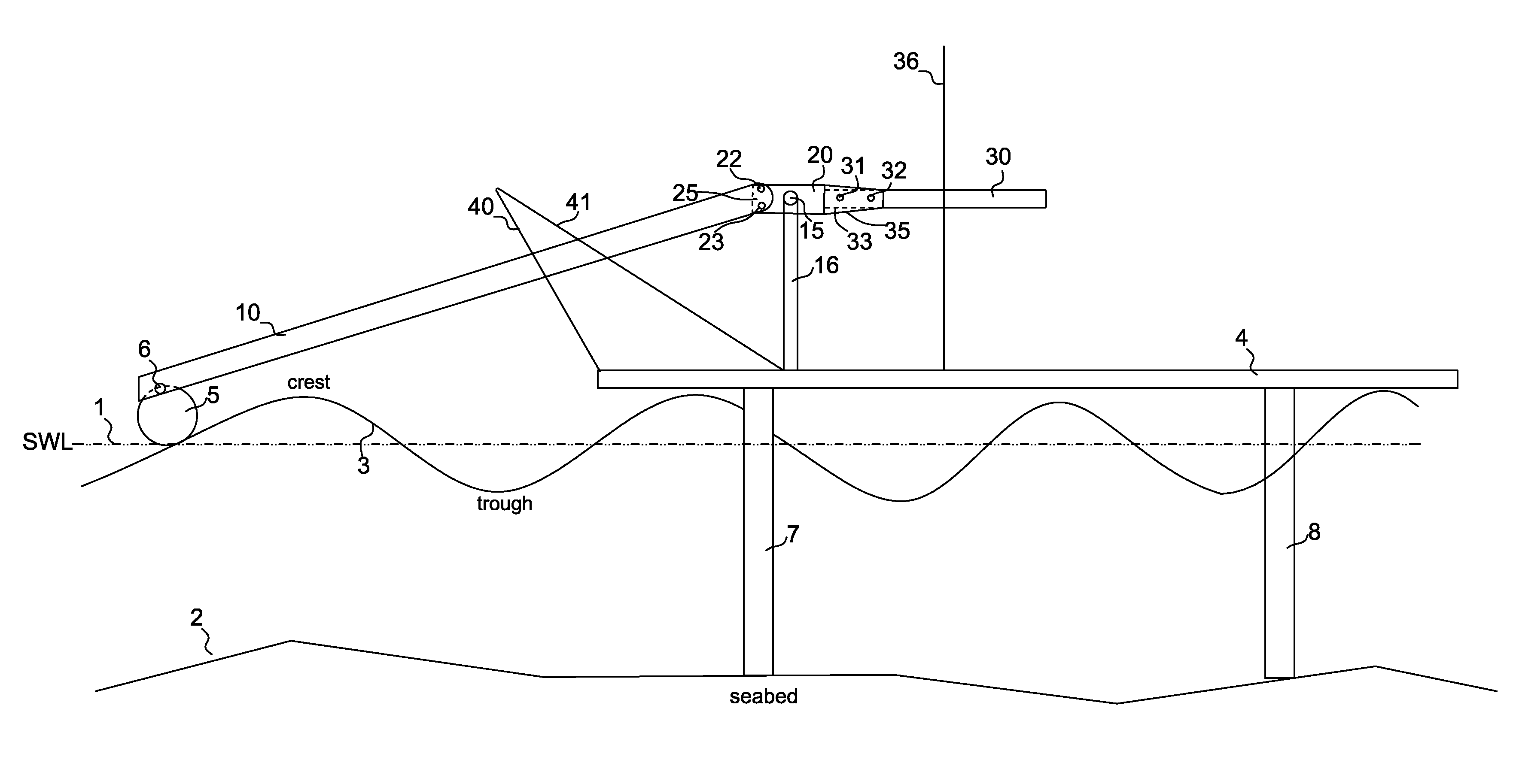
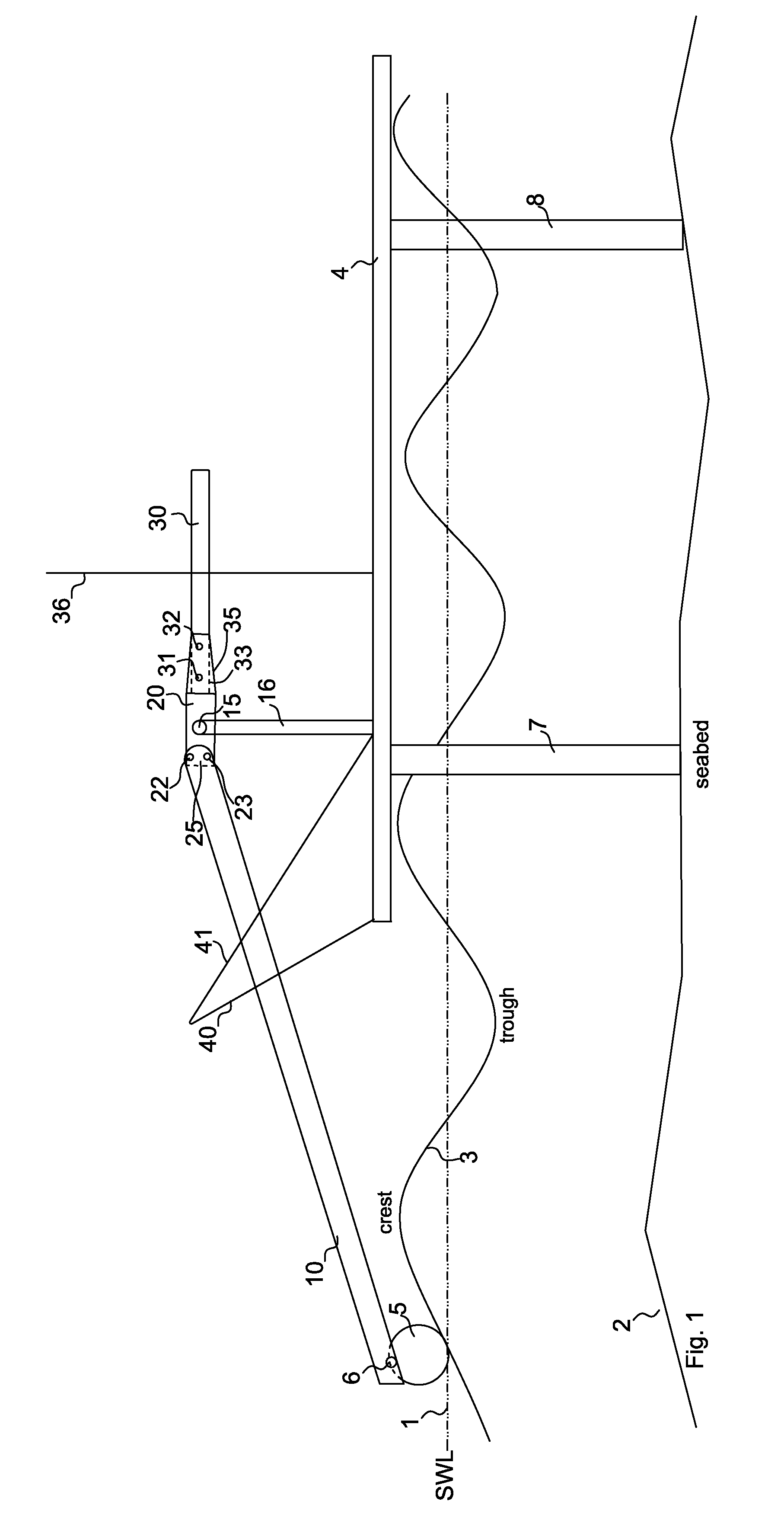
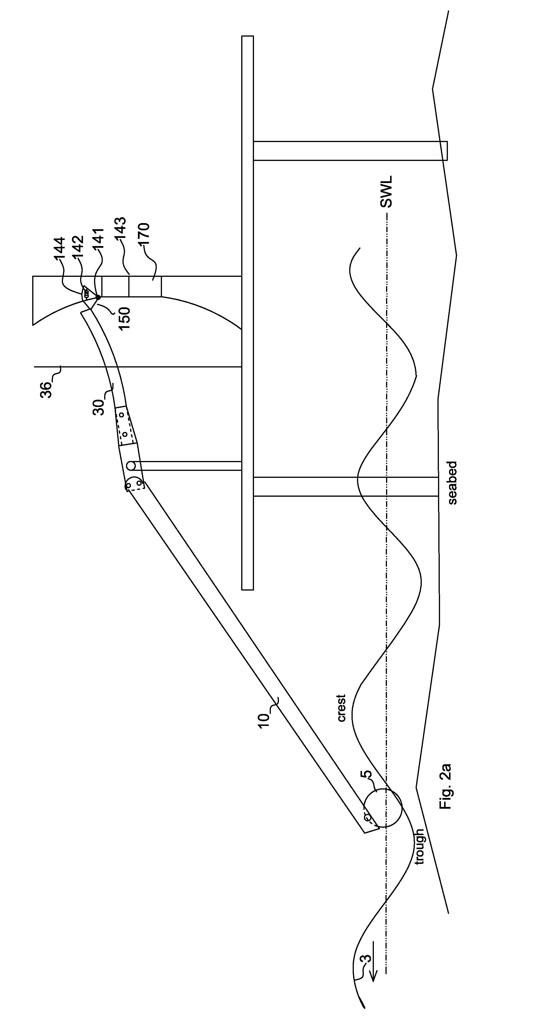
[0036]The device subject of this disclosure relates to a pivoting beam assembly with a float pivoting about a pivot to harness and transform the energy of ocean waves to different forms of energy. The pivoting beam assembly with float comprises a rigid beam, an elastic beam, a connector such as a sleeve connector and a buoyant float. The first end of the rigid beam is attached to the float and the second end is firmly connected to the one end of the connector; the other end of the connector is firmly connected to the first end of the elastic beam.

[0037]The pivoting beam assembly with float pivots about a pivot with the reciprocating up and down motion of the ocean waves. The pivot is positioned on a stationary place, such as a platform, above the surface of the ocean or on shore land, or on a breakwater. Also, the platform may be on top of a considerably heavier floating platform. Typically, when the float is at the Still Water Level (SWL), the elastic beam is positioned horizontall...


PUM


Abstract

A device comprising a float (5) and a pivoting assembly of a rigid beam (10) and an elastic beam (30, firmly connected to each other, pivoting about a stationary point (15). The device transforms the rise and falls of the ocean waves into usable mechanical energy. In one embodiment, the elastic beam is latched into a latch mechanism (150). The latch mechanism obstructs the elastic beam to continue moving. The elastic beam deflects and accumulates potential power. When the elastic beam is released, it moves with a high speed and momentum. In another embodiment this momentum is utilized to counter-rotate an electric generator's two rotors (251, 252).
A method of transforming the energy of a mass in reciprocating motion to electrical power.

Description

CROSS-REFERENCE TO RELATED APPLICATIONS[0001]This application claims the benefit of U.S. provisional patent application Ser. No. 61 / 408,011, filed 2010 Oct. 29 by the present inventor. The application also claims the benefit of U.S. provisional patent application Ser. No. 61 / 414,246, filed 2010 Nov. 16 by the present inventor.BACKGROUND OF THE INVENTION[0002]The following is a tabulation of some prior art that presently appears relevant:U.S. PATENTS[0003]Pat. No.Kind CodeIssue DatePatentee7,468,563B22008-12-23Torch7,444,810B22008-11--4Olson7,352,073B22008-04--1Ames7,012,340B22006-03-14Yi4,931,6621990-06--5BurtonFIELD OF USE[0004]The present device transforms the rise and fall of ocean waves to different forms of energy. The device includes a float, a rigid beam and an elastic beam which is forced to deflect when it reaches stop means or latch means while it pivots.DESCRIPTION OF THE PRIOR ART[0005]Harnessing renewable energy from the ocean has inspired the design of many ocean wave ...

Claims


Application Information

Patent Timeline
IPC IPC(8): F03B13/18
CPCF03B13/16F03B13/18Y02E10/38F03B13/00F03B13/12H02P9/04F03B13/10Y02E10/20Y02E10/30
Inventor VAMVAS, VASSILIOS
Owner VASSILIOS VAMVAS
Why Eureka
Try Eureka