Beam splitter for 3D camera, and 3D image acquisition apparatus employing the beam splitter

a beam splitter and camera technology, applied in the field of beam splitter for 3d camera and 3d image acquisition apparatus, can solve the problems of inaccurate distance information, difficulty in obtaining accurate distance information using the above methods, and mismatch between color image and depth imag

Active Publication Date: 2012-05-03
SAMSUNG ELECTRONICS CO LTD
View PDF8 Cites 43 Cited by
  • Summary
  • Abstract
  • Description
  • Claims
  • Application Information

AI Technical Summary

Problems solved by technology

However, according to the aforementioned methods, the accuracy of the distance information deteriorates as the distance between the 3D camera and the object becomes great.
Also, it is difficult to obtain accurate distance information using the aforementioned methods because they are dependent upon a status of the surfaces of the object in question.
However, in such a case, a mismatch may occur between the color image and the depth image due to a mismatch between an optical axis of an optical system used to obtain the color image, and an optical axis of an optical system used to obtain the depth image.
However, in a case in which a reflection-type modulator is used, a huge amount of light loss may occur in a beam splitter, and this light loss may decrease a signal-to-noise ratio (SNR) so that the light loss may deteriorate the accuracy of the depth information.

Method used


Image

  • Beam splitter for 3D camera, and 3D image acquisition apparatus employing the beam splitter
  • Beam splitter for 3D camera, and 3D image acquisition apparatus employing the beam splitter
  • Beam splitter for 3D camera, and 3D image acquisition apparatus employing the beam splitter

Examples


Embodiment Construction

[0050]Reference will now be made in detail to embodiments of a beam splitter for a 3D camera, and a 3D image acquisition apparatus employing the beam splitter, examples of which are illustrated in the accompanying drawings. In the drawings, like reference numerals denote like elements, and the size of each component may be exaggerated for clarity.

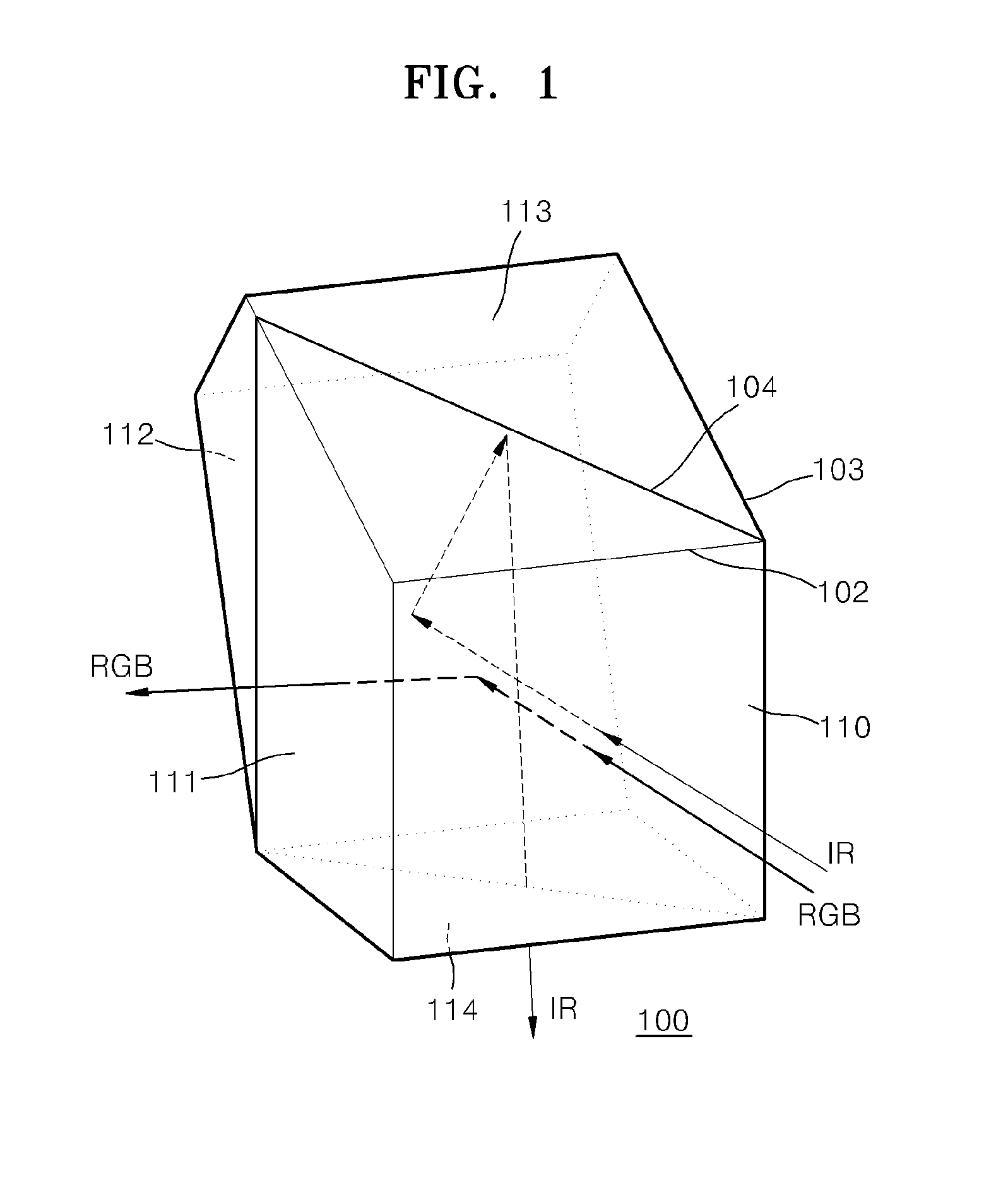
[0051]FIG. 1 is a perspective view of a beam splitter 100 according to an embodiment. Referring to FIG. 1, the beam splitter 100 may have the shape of a pentaprism. The pentaprism is a polyhedral prism that is formed of an optically transparent material including glass and which has a pentagon-shaped cross-section. The beam splitter 100 may be formed to have the shape of a pentaprism by adhering at least two polygonal prisms to each other. The beam splitter 100 may be formed by adhering an inclined surface of a first part prism 102 having inclined surfaces to an inclined surface of a second part prism 103 having inclined surfaces. According...


PUM


Abstract

A beam splitter and a 3D image acquisition apparatus including the beam splitter are provided. The beam splitter includes a light incident surface on which light having a first wavelength and light having a second wavelength are incident; a beam splitting surface which is inclined to the light incident surface and reflects the light having the first wavelength and transmits the light having the second wavelength; a first light exit surface through which the light having the first wavelength reflected from the beam splitting surface exits; a first reflective surface which reflects the light having the second wavelength transmitted by the beam splitting surface; a second reflective surface which reflects the light having the second wavelength reflected from the first reflective surface; and a second light exit surface through which the light having the second wavelength reflected from the second reflective surface exits.

Description

CROSS-REFERENCE TO RELATED APPLICATIONS[0001]This application claims priority under 35 U.S.C. §119(a) from Korean Patent Application No. 10-2010-0107012, filed on Oct. 29, 2010, in the Korean Intellectual Property Office, the disclosure of which is incorporated herein in its entirety by reference.BACKGROUND[0002]1. Field[0003]The present disclosure relates to a beam splitter for a 3D camera, and a 3D image acquisition apparatus such as a 3D camera, wherein the beam splitter is capable of separating a color image and a depth image, which are incident via a same incident surface, to proceed along different paths, and wherein the 3D image acquisition apparatus is capable of simultaneously capturing a color image and a depth image by using one lens and the beam splitter.[0004]2. Description of the Related Art[0005]Due to the development and increase in use of 3D display apparatuses, the development of 3D content has become important. Thus, research has been conducted into providing a 3D...

Claims


Application Information

Patent Timeline
Patent Type & Authority Applications(United States)
IPC IPC(8): G02B27/14H04N13/02G01S17/894
CPCG01S7/4811G01S17/89H04N5/2254H04N5/33G02B27/1013G02B27/141G03B15/03G03B35/08G01S17/894A61B1/046H04N23/55G02B5/282G02B5/30G02B27/10G02B27/283G02B27/286G09G3/003
Inventor YOU, JANG-WOOPARK, YONG-HWACHO, YONG-CHUL
Owner SAMSUNG ELECTRONICS CO LTD
Why Eureka
Try Eureka