Multi-beam illumination system and method of illumination

a multi-beam illumination and beam technology, applied in the field of multi-beam illumination systems and a method of illumination, can solve the problems of only being changeable, not offering the user the functionality of changing the shape of the illumination image, and the direction of the beam is fixed, so as to facilitate the provision and manipulation, and the brightness of the illumination image may be established efficiently.

Inactive Publication Date: 2012-05-03
SIGNIFY HLDG BV +1
View PDF0 Cites 14 Cited by
  • Summary
  • Abstract
  • Description
  • Claims
  • Application Information

AI Technical Summary

Benefits of technology

[0012]The multi-beam illumination system according to the invention may thus provide a flexible illumination system, allowing defining the projection images, and hence the illumination image, with a lot of freedom. In particular, it may allow making illumination images of different shapes and different colors, defined especially by the (color of the) light beams and the segment patterns, thus providing a light effect of a shape and / or color to an object illuminated by means of the illumination image. Different parts of the illumination image can each have their own color. These light effects can be static as well as dynamic, i.e. time-varying, depending on the type and characteristics of the panel used.
[0080]According to another aspect, the invention provides an illumination method using a multi-beam illumination system according to any one of the embodiments described above. The method may provide a convenient manner of defining and / or changing the projection image in illumination.

Problems solved by technology

A disadvantage of many illumination systems of the prior art may for instance be that the known color-variable lamps, such as color-variable LED-lamps, can only generate a beam with a fixed and pre-determined beam shape, and thus a fixed and pre-determined size of the illuminated area (which may further be referred to as a “illumination image”) on a surface, e.g. a wall.
Therefore, such lamps do not offer the user the functionality of changing the shape of the illumination image.
Another disadvantage of prior art apparatus may be that the direction of the beam is fixed, and may only be changeable by changing the orientation of the lamp itself.
Furthermore, it may be found undesirable by users that known lamps can only provide one illumination image as a single-color spot at a time, i.e. when two different colors are wanted side-by-side, the user needs to use two lamps, each adjusted to an individual color, to provide the two colors.

Method used


Image

  • Multi-beam illumination system and method of illumination
  • Multi-beam illumination system and method of illumination
  • Multi-beam illumination system and method of illumination

Examples


Embodiment Construction

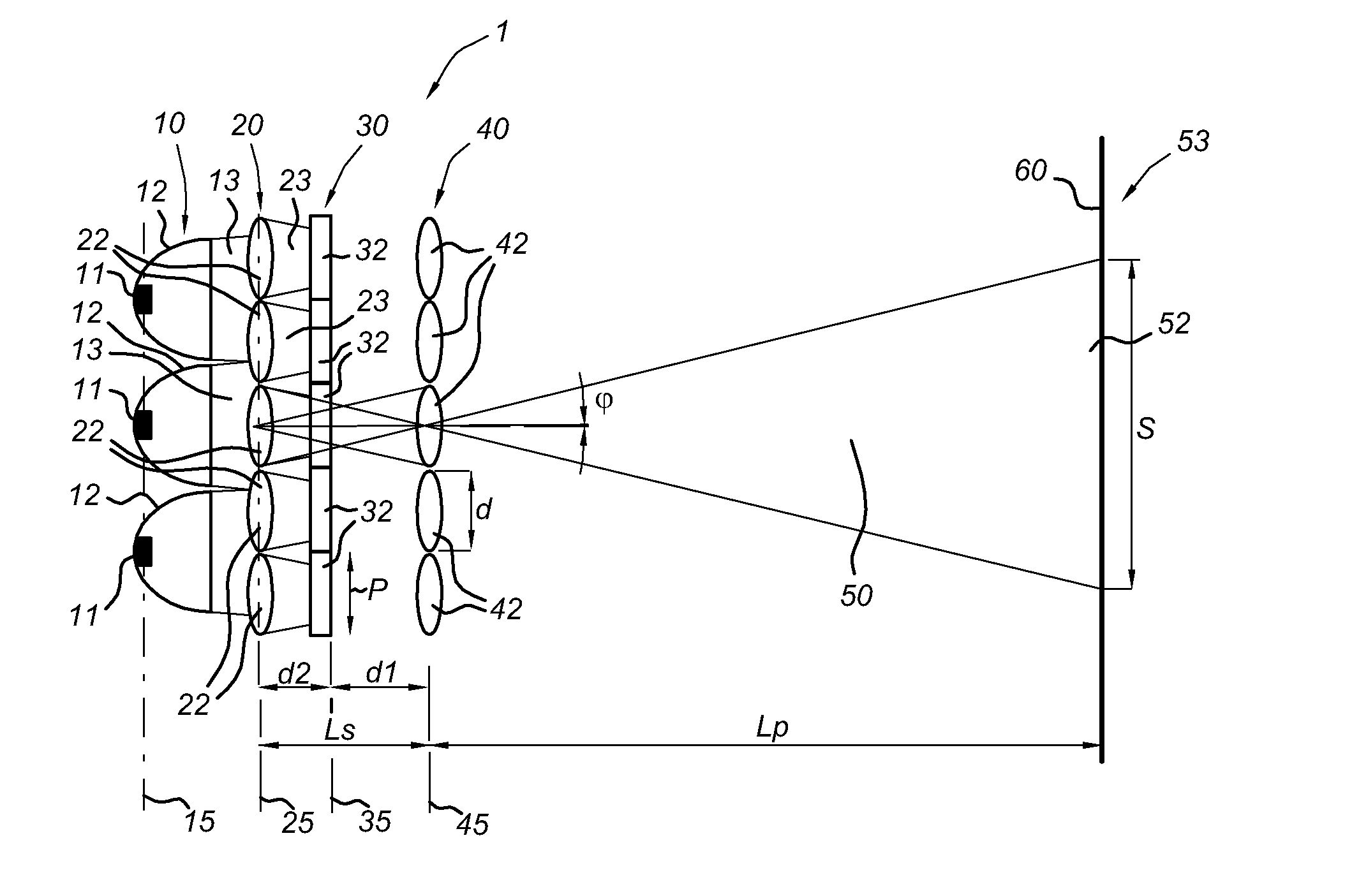
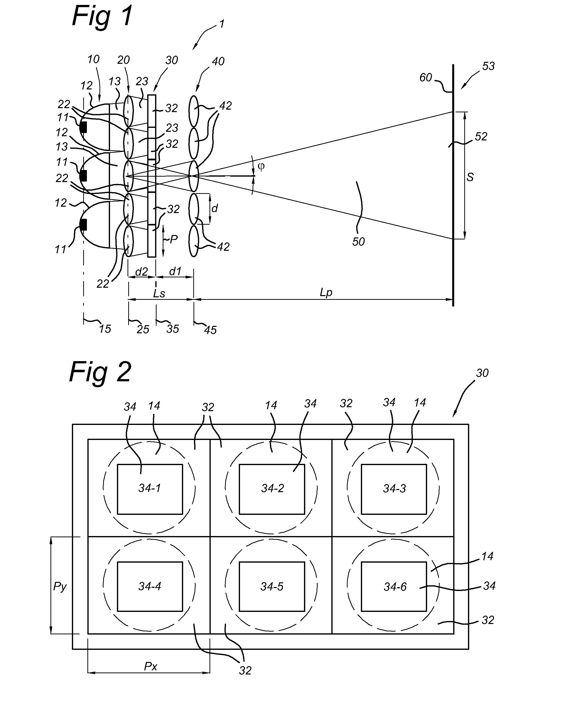
[0100]FIG. 1 schematically depicts an exemplary embodiment of a multi-beam illumination system 1 according to the invention. The multi-beam illumination system 1 is arranged at a projection distance Lp from a projection surface 60. The projection distance Lp may also be referred to as “image distance”. The multi-beam illumination system 1 has an array 10 of light sources 11 with collimating optics 12. More specifically, the embodiment shown in FIG. 1 has a LED array 10 of LED light sources 11 with collimating optics 12. Alternative embodiments may use alternative types of light sources, such as e.g. incandescent lamps, discharge lamps or lasers. However, in the description below, we will refer to LED light sources and LED light beams, in order not to obscure the description. The collimating optics 12 comprises collimator lenses and / or mirrors. The collimating optics 12 may be absent in alternative embodiments, and will thus further be referred to as optional collimating optics 12. D...


PUM


Abstract

The invention provides a multi-beam illumination system (1) for providing an illumination image (53). The multi-beam illumination system (1) has a plurality of light sources (11) with optional collimating optics (12), arranged to generate a plurality of light beams (13); a panel (30) comprising a plurality of panel segments (32) in a panel plane (35) at a first distance (d1) and arranged to contain a plurality of segment patterns (34) on the corresponding panel segments (32); and an imaging lens array (40) comprising a plurality of imaging lenses (42) in an imaging lens plane (45) parallel to the panel plane (35). Each imaging lens (42) of the imaging lens array (40) is arranged to image a corresponding segment pattern (34) of the plurality of segment patterns (34) into a respective projection image (52) of a plurality of projection images (52). The plurality of projection images (52) over-lap at a predetermined image distance (Lp) and form the illumination image (53).

Description

FIELD OF THE INVENTION[0001]The invention relates to a multi-beam illumination system and a method of illumination.BACKGROUND OF THE INVENTION[0002]Traditionally, lighting systems have mainly been used for general illumination using white light, e.g. ceiling lighting systems using incandescent or fluorescent lighting, as well as for task lighting using white light, e.g. an incandescent or halogen spot lamp. Recently, lighting systems providing colored light have been introduced in professional and consumer markets, and these lighting systems are receiving more and more market interest, in particular for decorative purposes, as well as for e.g. creating specific atmospheres by using specific colors, but also for functional reasons. In particular, recent progress in the brightness, lumen efficacy and affordability of solid state light sources, notably light-emitting-diodes (LEDs), have made LEDs more and more suited for making professional as well as consumer lighting systems, in a wi...

Claims


Application Information

Patent Timeline
Patent Type & Authority Applications(United States)
IPC IPC(8): F21V5/04H05B44/00
CPCH05B33/0803H05B45/20G03B21/005G03B21/001F21S2/005F21V5/007G03B21/142G03B21/53F21Y2105/14F21Y2115/10H05B45/30
Inventor VISSENBERG, MICHEL CORNELIS JOSEPHUS MARIEDEKKER, TIMHIKMET, RIFAT ATA MUSTAFAVAN GORKOM, RAMON PASCALKRIJN, MARCELLINUS PETRUS CAROLUS MICHAELWILLEMSEN, OSCAR HENDRIKUS
Owner SIGNIFY HLDG BV
Why Eureka
Try Eureka