Speaker device and method for forming speaker device
a speaker device and speaker technology, applied in the field of speaker devices, can solve the problems of not giving sufficient consideration, and achieve the effect of good non-directional reproduced sound field for listeners
- Summary
- Abstract
- Description
- Claims
- Application Information
AI Technical Summary
Benefits of technology
Problems solved by technology
Method used
Image
Examples
first preferred embodiment
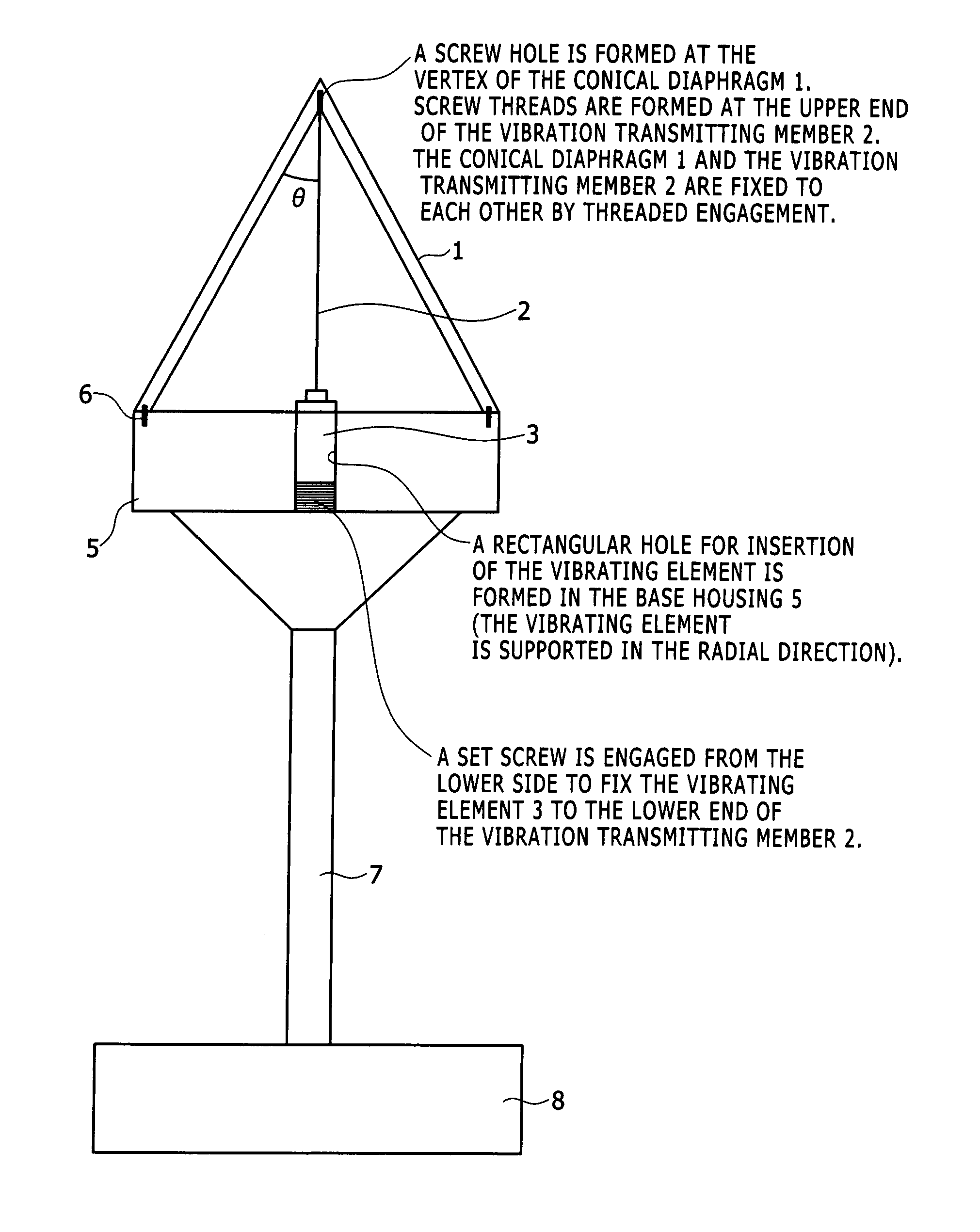
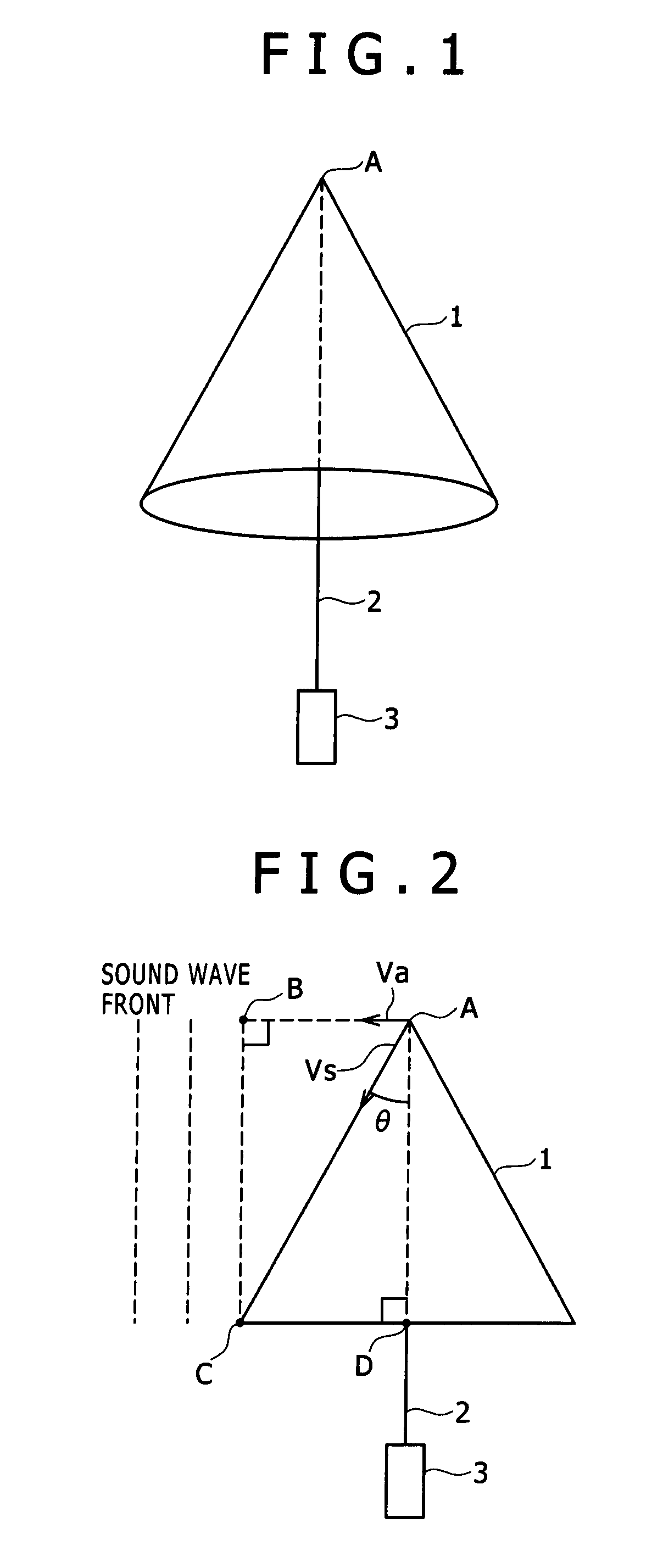
[0050]FIG. 1 is a view for illustrating the external appearance of an excitation type speaker device according to a first preferred embodiment of the present invention. As shown in FIG. 1, the speaker device according to the first preferred embodiment is composed of a conical diaphragm 1, a vibration transmitting member 2, and a vibrating element (actuator) 3.
[0051]The conical diaphragm 1 is used as an acoustic diaphragm, and it is formed of epoxy resin, for example, so as to have a circular conical shape. In the first preferred embodiment, the conical diaphragm 1 has a thickness of about 3 mm, for example, and the inside of the conical diaphragm 1 is vacant. That is, the conical diaphragm 1 has an isosceles triangular shape as viewed in side elevation, and the circular base of the conical diaphragm 1 is formed with a circular (exactly round) opening.
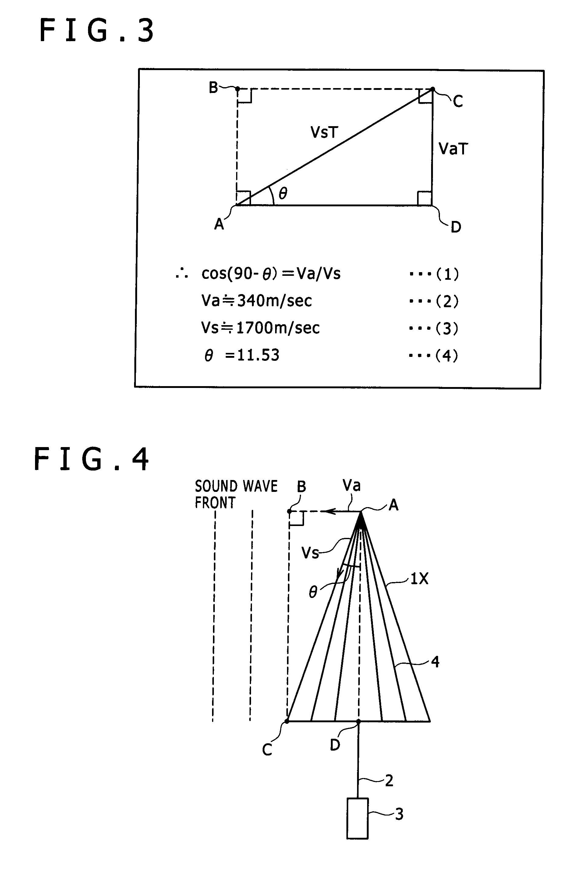
[0052]When a perpendicular is dropped from the vertex A of the conical diaphragm 1 to the base thereof, this perpendicular passes thro...
second preferred embodiment
[0152]FIG. 11 is a view for illustrating an excitation type speaker device according to a second preferred embodiment of the present invention. More specifically, FIG. 11 is a side view of the speaker device according to the second preferred embodiment.
[0153]In FIG. 11, parts similar to those of the speaker device according to the first preferred embodiment shown in FIGS. 1 to 3 are denoted by the same reference numerals and the detailed description thereof will be omitted herein.
[0154]The speaker device according to the second preferred embodiment shown in FIG. 11 is composed of two conical diaphragms 1a and 1b, a vibration transmitting member 2, and a vibrating element 3.
[0155]As in the case of the conical diaphragm 1 according to the first preferred embodiment shown in FIG. 3, each of the conical diaphragms 1a and 1b is formed so that the angle θ between the axis and the side surface of the conical diaphragm 1a or 1b is adjusted according to the sound velocity in the air and the ...
third preferred embodiment
[0174]FIGS. 13 to 16 are views for illustrating various configurations of a speaker device according to a third preferred embodiment of the present invention. The speaker device according to the third preferred embodiment employs a plurality of conical diaphragms as similar to the speaker device according to the second preferred embodiment shown in FIG. 12, but different from the speaker device according to the second preferred embodiment in the way of arrangement of the conical diaphragms.
First Example of Third Preferred Embodiment
[0175]FIG. 13 is a view for illustrating a speaker device according to a first example of the third preferred embodiment. As shown in FIG. 13, the speaker device according to this example includes a conical diaphragm 1c formed of magnesium and a conical diaphragm 1d formed of paper (e.g., cone paper).
[0176]As in the conical diaphragm 1 according to the first preferred embodiment shown in FIG. 3, the angle θ1 between the axis of the conical diaphragm 1c an...
PUM
| Property | Measurement | Unit |
|---|---|---|
| thickness | aaaaa | aaaaa |
| diameter | aaaaa | aaaaa |
| sound velocity | aaaaa | aaaaa |
Abstract
Description
Claims
Application Information
 - R&D
- Intellectual Property
- Life Sciences
- Materials
- Tech Scout
- Unparalleled Data Quality
- Higher Quality Content
- 60% Fewer Hallucinations
Browse by: Latest US Patents, China's latest patents, Technical Efficacy Thesaurus, Application Domain, Technology Topic, Popular Technical Reports.
© 2025 PatSnap. All rights reserved.Legal|Privacy policy|Modern Slavery Act Transparency Statement|Sitemap|About US| Contact US: help@patsnap.com


