Check patentability & draft patents in minutes with Patsnap Eureka AI!

Apparatus and method for dispensing flowable solid material

Inactive Publication Date: 2012-05-03
ENERGEX CORP
View PDF0 Cites 6 Cited by
  • Summary
  • Abstract
  • Description
  • Claims
  • Application Information

AI Technical Summary

Benefits of technology

[0010]One aspect of the invention is directed to a device for delivering flowable solid material from a first location to a second location. The device has a receiving end, a discharge end and an outlet opening. The receiving end receives the flowable solid material therein and the discharge end discharges the flowable solid material therefrom. The outlet opening is connected to an assembly which draws airflow from the device through the outlet opening. Airflow drawn from the device through the outlet opening draws fine contaminants associated with the flowable solid material into the assembly. The airflow drawn from the device is at least partially drawn in a direction which is divergent to the direction of the movement of the flowable solid material to reduce the speed of the flowable solid material and allow the flowable solid material to be discharged from the discharge end at a speed which will not damage the flowable solid material and which will minimize the amount of fine contaminants introduced to the air surrounding the discharge end.
[0011]Another aspect of the invention is directed to a delivery system for delivering flowable solid material from a first location to a second location. The delivery system has intake tubing, a discharge device, a blower assembly and a draw assembly. The intake tubing is positioned to cooperate with the flowable solid material at the first location. The discharge device is positioned proximate the second location. The discharge device has a receiving end, a discharge end and an outlet opening. The receiving end is connected to the intake tubing for receiving the flowable solid material therein and the discharge end discharges the flowable solid material therefrom. The blower assembly is attached to the intake tubing and provides airflow through the intake tubing to move the flowable solid material from the first location to the discharge device. The draw assembly is attached to the outlet opening. The draw assembly draws airflow from the discharge device through the outlet opening. Airflow drawn from the device through the outlet opening draws fine contaminants associated with the flowable solid material into the draw assembly. The airflow drawn from the device is at least partially drawn in a direction which is divergent to the direction of the movement of the flowable solid material to reduce the speed of the flowable solid material and allow the flowable solid material to be discharged from the discharge end at a speed which will not damage the flowable solid material and which will minimize the amount of fine contaminants introduced to the air surrounding the discharge end.
[0012]Another aspect of the invention is directed to a method for delivering flowable solid material from a first location to a second location. The flowable solid material is moved into a receiving end of a discharge apparatus through the use of an airflow stream. The airflow stream and fine contaminants are drawn through an outlet opening. The flowable solid material is then discharged from a discharged end of the discharge apparatus. Drawing the airflow stream through the outlet opening draws the airflow in a direction which is partially divergent from the direction of the movement of the flowable solid material to reduce the speed of the flowable solid material and allow the flowable solid material to be discharged from the discharge end at a speed which will not damage the flowable solid material.
[0013]The delivery system, discharge device and method of the present invention have several advantages. Due to the reverse pull applied to the flowable solid material by the vacuum stream, the integrity of the flowable solid material is maintained, as the flowable solid material does not encounter forces or velocities that cause the material to break apart or degrade, particularly as discharge. Another advantage is the elimination of airborne dust or other fine contaminants being released into the surrounding environment, thereby eliminating a threat to the safety of workers and consumers. As the fine contaminants are effectively removed from the flowable solid material at several locations, the discharge of the flowable solid material does not cause the fine contaminants to be released. Additionally, due to the use of the vacuum through the intake tube, the loss of material through damage to the intake tube when transferring from one location to another location is essentially eliminated.

Problems solved by technology

Airflow drawn from the device through the outlet opening draws fine contaminants associated with the flowable solid material into the assembly.
Airflow drawn from the device through the outlet opening draws fine contaminants associated with the flowable solid material into the draw assembly.

Method used


Image

  • Apparatus and method for dispensing flowable solid material
  • Apparatus and method for dispensing flowable solid material
  • Apparatus and method for dispensing flowable solid material

Examples


Embodiment Construction

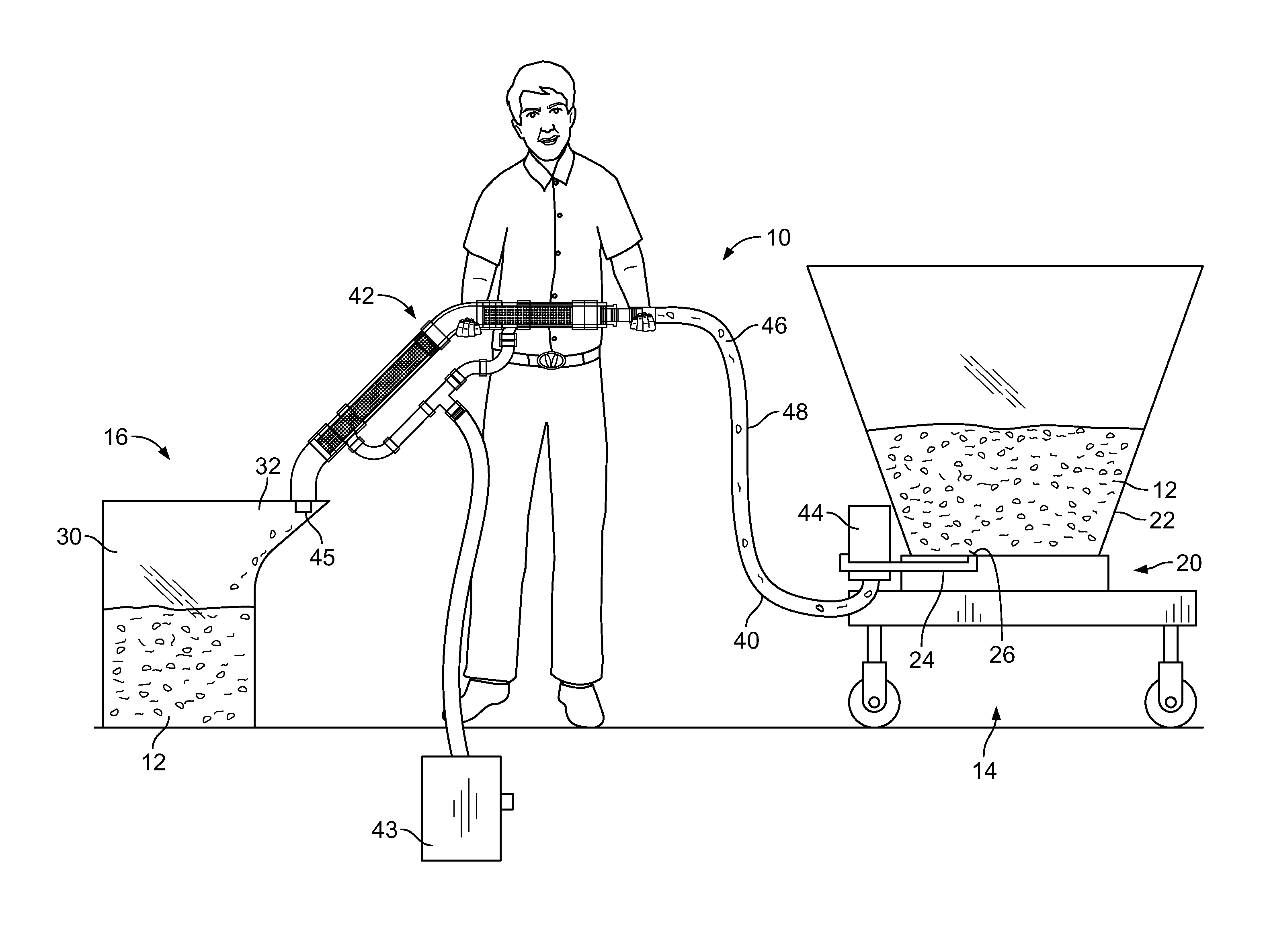
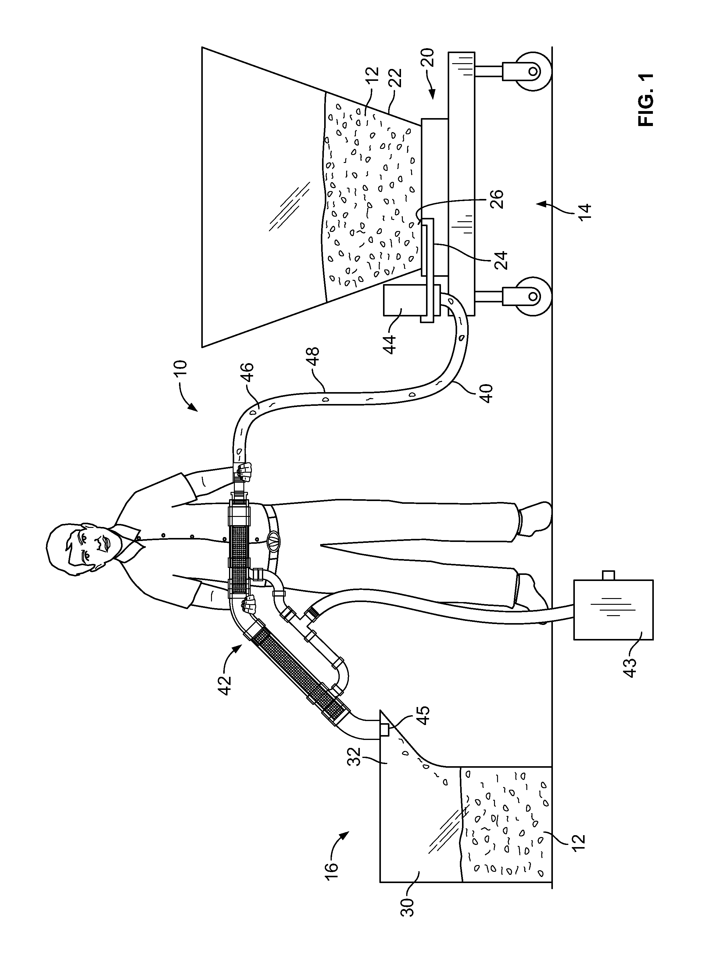
[0022]Various industries and consumers make use of a variety of flowable solid materials, which include, but are not limited to, friable solid materials. In particular, consumers use solid particulate fuels such as wood pellets or grains for heating. The delivery of such solid particulate fuels or flowable solid materials from a first location, such as a transport vehicle, to a second location, such as a storage bin, presents various concerns. One concern relates to the integrity of the pellets or other flowable solid material. As the material is transported, it is desirable to transport the material in a manner that does not cause the material to break apart or degrade. Another concern relates to the generation and release of airborne dust or other fine contaminants posing a threat to the safety of workers and consumers. Additionally, the loss of material through spillage from damage to the equipment when transferring from one location to another location is always a concern.

[0023]...


PUM


Abstract

The invention is directed to a method and device for delivering flowable solid material from a first location to a second location. The device has a receiving end which receives the flowable solid material therein and a discharge end which discharges the flowable solid material therefrom. An outlet opening is connected to a vacuum assembly which draws airflow from the device through the outlet opening, thereby drawing fine contaminants associated with the flowable solid material into the vacuum assembly. The airflow drawn from the device reduces the speed of the flowable solid material, allowing the flowable solid material to be discharged from the discharge end at a speed which will not damage the flowable solid material and which will minimize the amount of fine contaminants introduced to the air surrounding the discharge end.

Description

FIELD OF THE INVENTION[0001]The present invention relates to a system and device for transferring flowable solid material. Specifically, in the preferred applications the invention concerns an apparatus and method for transfer of flowable solid material from one location to another.BACKGROUND OF THE INVENTION[0002]Systems which use flowable solid material (herein “flowable solids,”“particulates,” or variants thereof) are known. One illustration of this type of systems is a stove that burns solid particulate fuels such as wood products (e.g., pellets, chips, etc.), grains (e.g., shelled corn, barley, wheat, etc.), and pulverized coal for home heating are very popular. These stoves typically have a hopper or holding / storage bin for the fuel and a fuel supply or feed system that transports the fuel from the hopper to the fire chamber to be burned. Some examples of feed systems include reciprocal pushers utilizing a pusher block or flat plates welded together, rotating cups and / or auger...

Claims


Application Information

Patent Timeline
IPC IPC(8): B65G53/58
CPCB65G53/24B65G53/34
Inventor HOWLAND, BOBPEACHEY, LORENCRONIN, JIMBURROWS, JOHNBURTCH, ROBERT J.
Owner ENERGEX CORP
Features
  • R&D
  • Intellectual Property
  • Life Sciences
  • Materials
  • Tech Scout
  • Unparalleled Data Quality
  • Higher Quality Content
  • 60% Fewer Hallucinations
Learn More