Imaging catheter with rotatable array

a technology of ice catheter and rotating array, which is applied in the field of ice catheters, can solve the problems of limited use of ice catheters, limited current ice catheter technology, and large user time spent becoming facile with catheter steering mechanisms, etc., and achieves sufficient aperture size and corresponding image resolution, and facilitates more complex procedures.

Inactive Publication Date: 2012-05-03
WL GORE & ASSOC INC
View PDF25 Cites 31 Cited by
  • Summary
  • Abstract
  • Description
  • Claims
  • Application Information

AI Technical Summary

Benefits of technology

[0032]Next, the catheter may be rotated at the proximal end, or twisted, to effect rotation along the length thereof, wherein the distal end portion may be located in a third position (e.g., without additional advancement of the catheter into the patient). Finally, the distal end portion may be rotated relative to the distal end of the catheter body to yield an image signal for processing (e.g., without manipulation of the catheter body). The noted four steps may be carried in any order, and repeated, any number of times.
[0033]As may be appreciated, the present invention is of particularly apt for catheter applications which may benefit from the capability to move the transducer array independent of a catheter body. Of particular benefit is the capability that allows a transducer array to be rotated relative to an axis (e.g., a center axis) of the catheter extending distally from a distal end of the catheter, wherein a panning motion may be realized. This panning motion provides the capability to rotate the transducer array in a 2D ICE catheter to capture multiple imaging views from a single catheter body position. As noted, this same panning capability may also be beneficial in a 3D catheter with a wobble mechanism interfaced with the transducer. In the case of the 3D catheter, the wobble mechanism may generate the 3D scan volume by oscillating the t

Problems solved by technology

Current ICE catheter technology does have limitations though.
Conventional ICE catheters are limited in that the clinician must repeatedly manipulate the catheter in order to capture multiple image planes within the anatomy.
The catheter manipulation needed to obtain specific

Method used


Image

  • Imaging catheter with rotatable array
  • Imaging catheter with rotatable array
  • Imaging catheter with rotatable array

Examples


Embodiment Construction

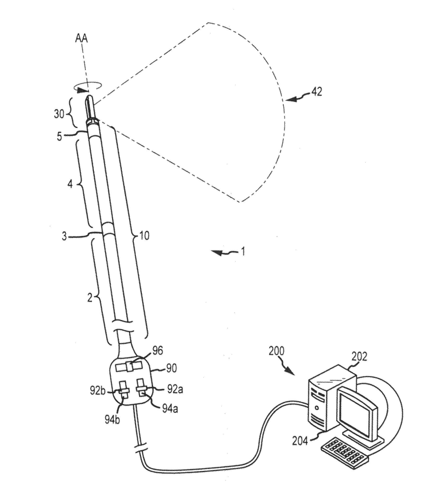
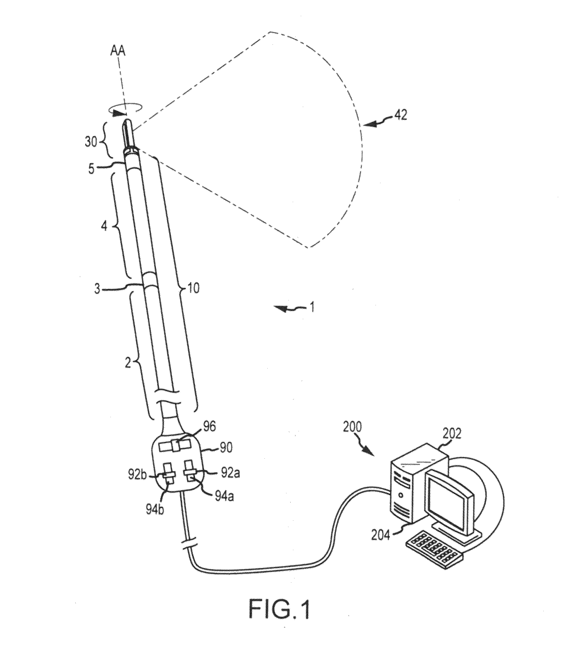
[0059]FIGS. 1-3 illustrate one embodiment of an imaging catheter 1. The imaging catheter 1 may include a catheter body 10 and a distal end portion 30 supported by and selectively rotatable relative to a distal end of the catheter body 10 at an interface therebetween.

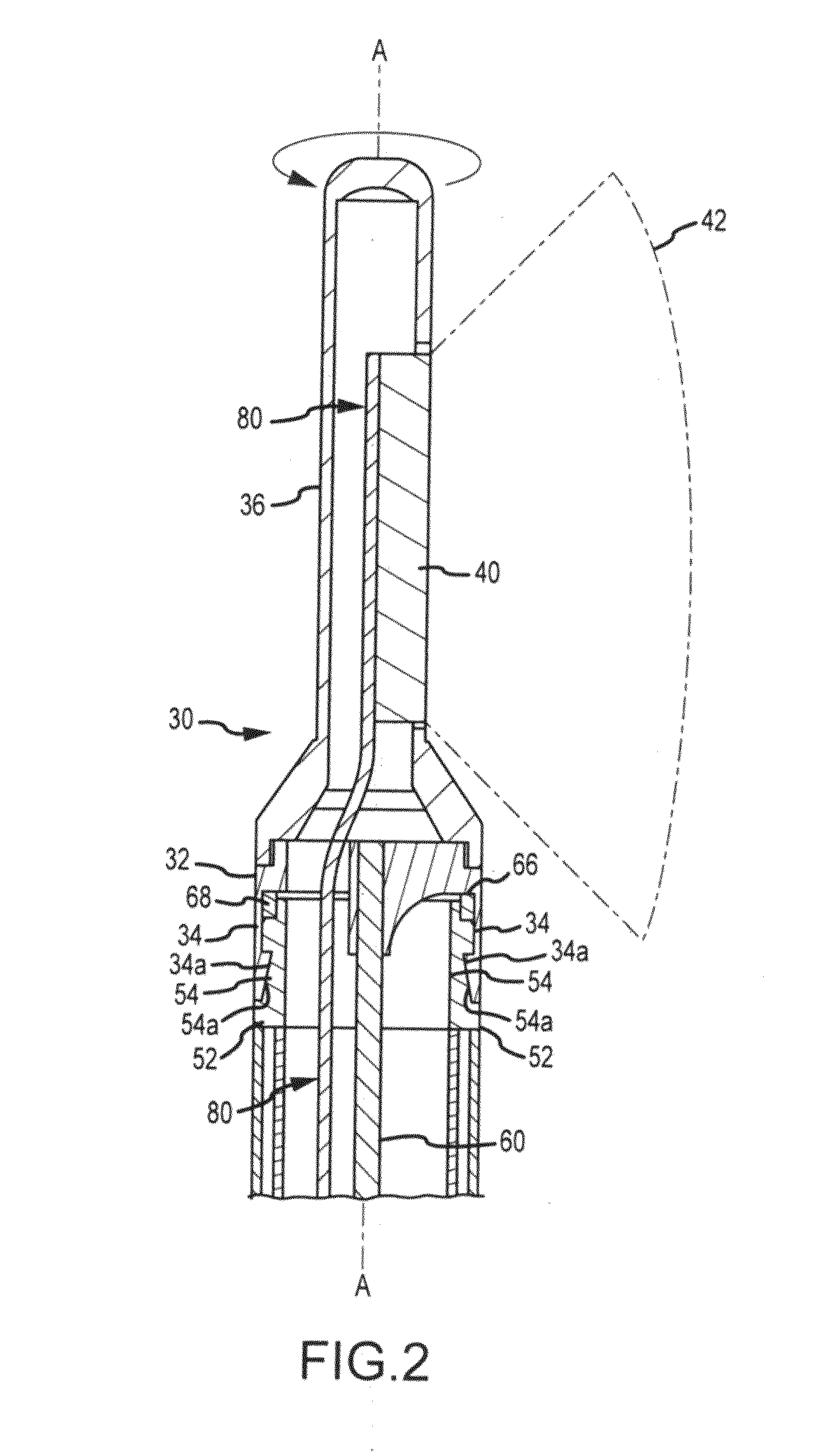
[0060]As shown in FIG. 2, the distal end portion 30 of the catheter 1 may include a first interface member 32 and a housing member 36 supportably interconnected to the first interface member 32. In turn, a transducer array 40 (e.g., an ultrasound transducer array) may be rotatably supported by the distal end portion 30. The transducer array 40 may be provided to have a predetermined imaging field 42. The predetermined imaging field 42 may be selectively rotated about axis AA. In the illustrated embodiment, axis AA coincides with a central axis of the distal end portion 30 and a central axis of the catheter body 10.

[0061]To facilitate the selective rotation of the distal end portion 30, a rotatable drive member 60 may be ...


PUM


Abstract

An imaging catheter is provided having a distal end portion selectively rotatable relative to a catheter body. A transducer array is supported by the distal end portion so that a corresponding imaging field may be selectively panned about an axis extending distally from the catheter body. The catheter may be advanced within a patient to a desired location. Optionally, the catheter may then be steered, or curved to position the transducer array. Optionally, the catheter may be rotated to further position the transducer array. Then, the imaging field may be panned without manipulation of the catheter body.

Description

RELATED APPLICATION[0001]This application claims priority to U.S. Provisional Patent Application No. 61 / 407,382, filed Oct. 27, 2010, entitled “IMAGING CATHETER WITH ROTATABLE ARRAY,” which application is incorporated herein by reference in its entirety.FIELD OF THE INVENTION[0002]The present invention relates to catheters, and more particularly to imaging catheters with enhanced positioning capabilities.BACKGROUND OF THE INVENTION[0003]Catheters are medical devices that may be inserted into a body vessel, cavity or duct, and manipulated utilizing a portion that extends out of the body. Typically, catheters are relatively thin and flexible to facilitate advancement / retraction along non-linear paths. Catheters may be employed for a wide variety of purposes, including the internal bodily positioning of diagnostic and / or therapeutic devices. For example, catheters may be employed to position internal imaging devices (e.g., ultrasound transducers).[0004]In this regard, use of ultrasonic...

Claims


Application Information

Patent Timeline
IPC IPC(8): A61B8/14
CPCA61B8/12A61B8/445A61B8/4461A61B8/0883
Inventor FRANKLIN, CURTISSHILLING, THOMAS W.DIETZ, DENNIS R.NORDHAUSEN, CRAIG T.DREHER, DENNISTOLT, THOMAS L.
Owner WL GORE & ASSOC INC
Why Eureka
Try Eureka