Carrier with integrated ducting

Active Publication Date: 2012-05-10
MAGNA INTERNATIONAL INC
View PDF41 Cites 68 Cited by
  • Summary
  • Abstract
  • Description
  • Claims
  • Application Information

AI Technical Summary

Benefits of technology

[0010]More particularly, each louver has a pair of seals, with one seal from one louver contacting a corresponding seal of a corresponding louver for preventing airflow through the aperture of the carrier. Each seal includes a slip coat for reducing the friction between the seals, as well as limiting binding between the louvers from ice formation on the surface of the seals, and improving wear resistance to dirt and debris during cycling.
[0011]In anot

Problems solved by technology

When the engine is substantially the same temperature as the surrounding environment and is turned on, the engine is the least fuel efficient (especially during start-up and the temperature of the surrounding environment is cold).
Furthermore, components designed to provide optimal cooling when the vehicle is new may operate differently after the vehicle has accumulated significant mileage.
This may occur due to various weather conditions, changes in the way the vehicle is operated in response to different drivers, or wear and tear on the vehi

Method used


Image

  • Carrier with integrated ducting
  • Carrier with integrated ducting
  • Carrier with integrated ducting

Examples


Embodiment Construction

[0041]The following description of the preferred embodiment(s) is merely exemplary in nature and is in no way intended to limit the invention, its application, or uses.

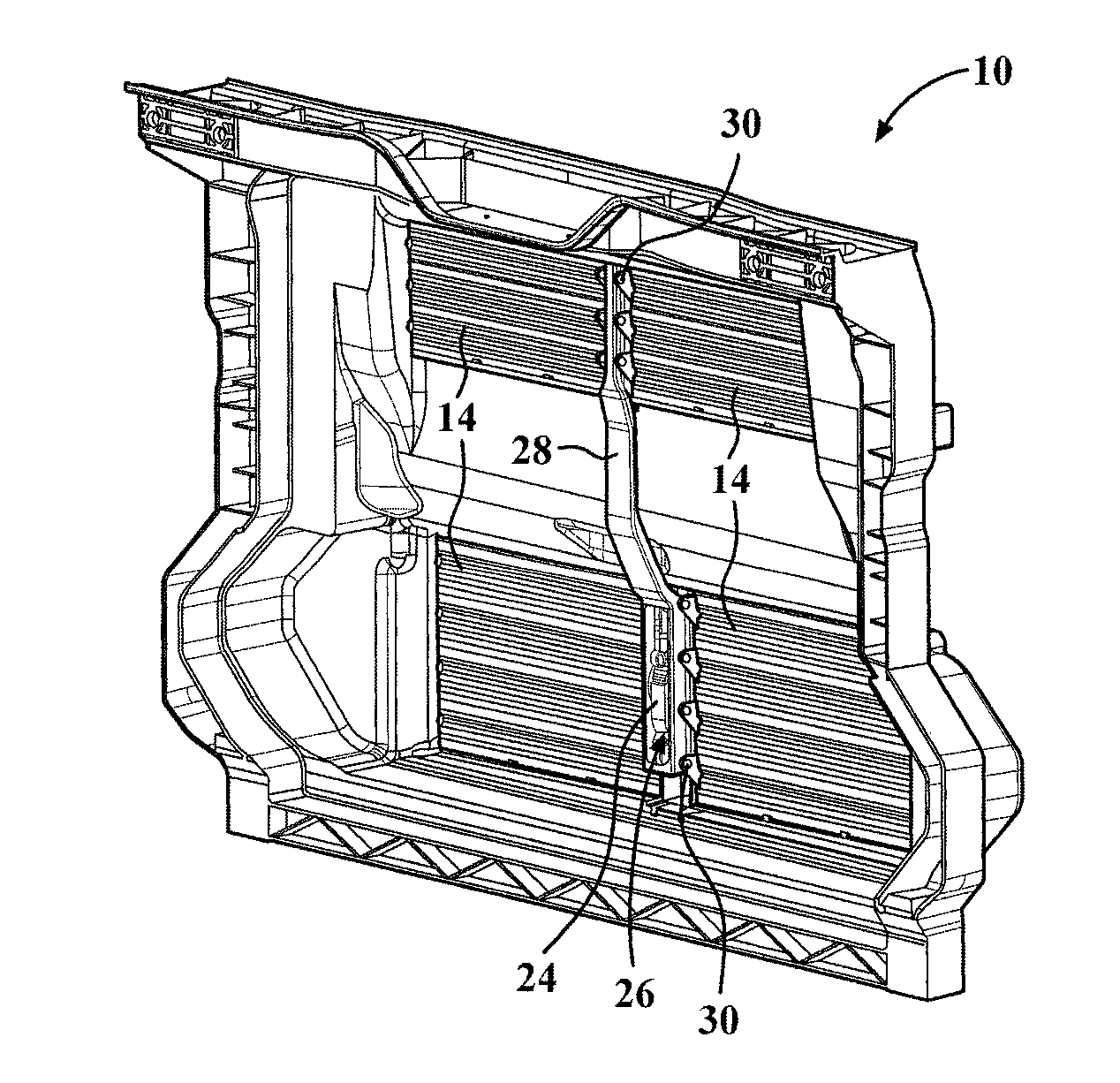
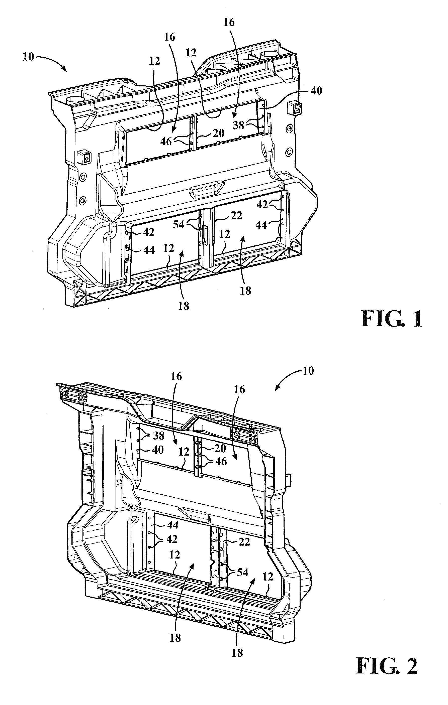
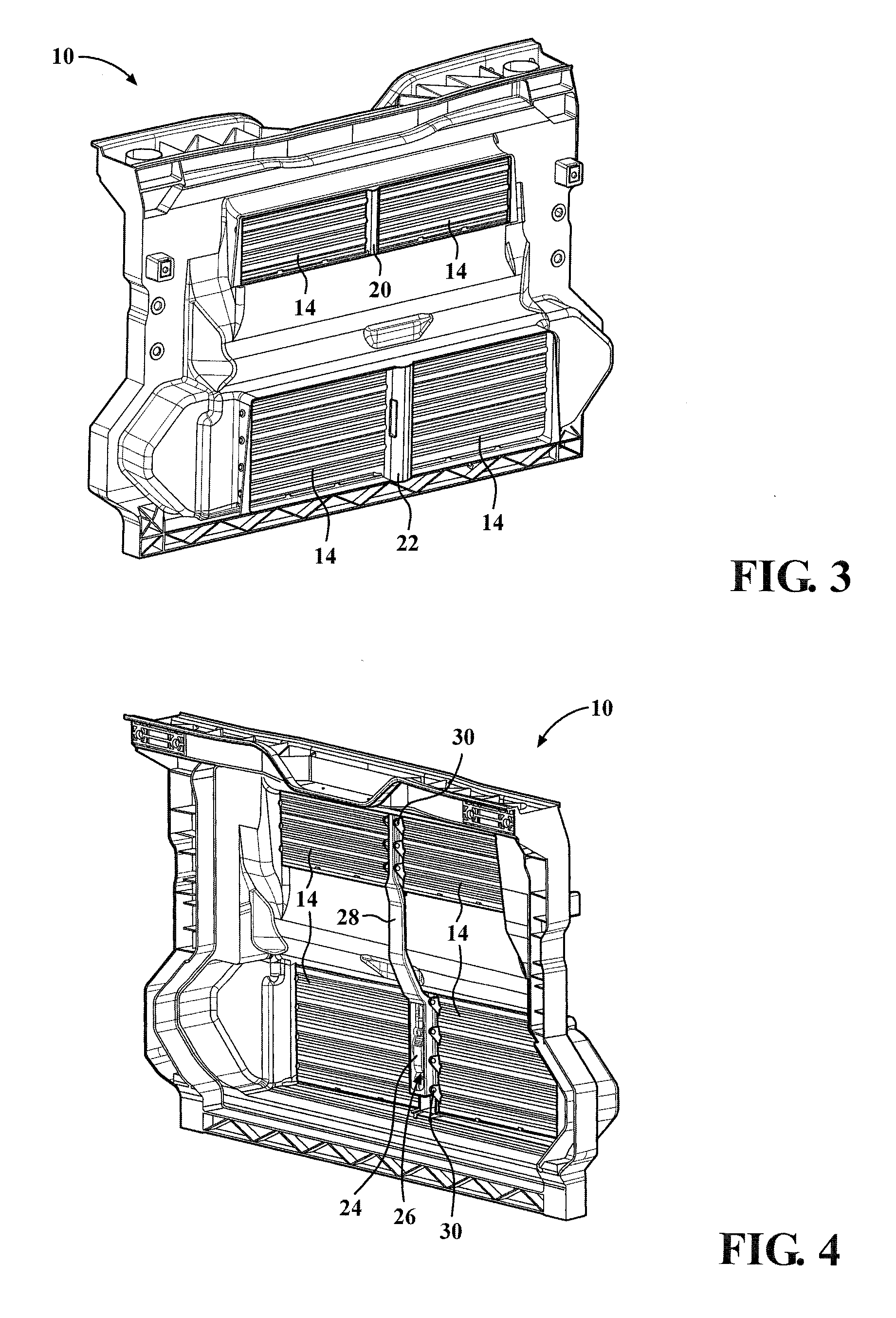
[0042]An embodiment of a carrier having integrated active ducting is shown in the Figures generally at 10. The carrier 10 is a single molded component, and includes various ports, flanges, support members, and the like operable for connection with the various components located inside an engine compartment, such as a radiator, fan shroud, washer fluid container, the vehicle chassis, body-in-white (BIW), and other similar components. While the carrier 10 is molded as shown, it is within the scope of the invention that the carrier 10 is operable to be molded having other shapes such that the carrier 10 of the present invention is able to be used with different types of vehicles.

[0043]The carrier 10 includes several apertures 12 which function as ducting and are operable for allowing air flow therethrough. The ducting al...


PUM

PropertyMeasurementUnit
Lengthaaaaaaaaaa
Structureaaaaaaaaaa
Flexibilityaaaaaaaaaa

Abstract

The present invention is directed to a carrier for an automobile with integrated active ducting. The carrier includes at least one aperture, and at least one louver rotatably mounted in the aperture. Also attached to the carrier is an actuator, and the actuator is connected to the louver. The actuator is operable for moving the louver between an open position and a closed position such that when the louver is in the open position, air flow passes through the aperture.

Description

CROSS-REFERENCE TO RELATED APPLICATIONS[0001]This application claims the benefit of U.S. Provisional Application No. 61 / 271,413, filed Jul. 21, 2009.FIELD OF THE INVENTION[0002]The present invention relates to a carrier for an automobile which has active ducting integrated with the carrier to provide greater control over the cooling of an automobile.BACKGROUND OF THE INVENTION[0003]Various attempts have been made to optimize the cooling of various automobile parts. Some of the various devices developed have been designed to control the air flow throughout the engine compartment of the automobile such that the desired amount of heat is transferred away from the engine, transmission, and other components which generate heat in order to maintain an optimal operating temperature.[0004]However, it is also desirable to bring the engine up to the normal operating temperature as soon as possible after engine start-up. When the engine is substantially the same temperature as the surrounding ...

Claims


Application Information

Patent Timeline
IPC IPC(8): B60H1/24B29C48/151
CPCB60K11/085B60R19/52F24F13/15B60R2019/525B62D25/084B60R2019/1886B29C48/0021B29C48/0022B29C48/151B60Y2410/113B60Y2410/123Y02T10/88B29K2023/12B29L2022/00B29L2031/748B60K11/04B62D25/085
Inventor CRANE, MICHAEL W.PILETTE, THOMASGUSCHEWSKI, NORMAN
Owner MAGNA INTERNATIONAL INC
Why Eureka
Try Eureka