Intrauterine device and inserter for the same

a technology of intrauterine device and inserter, which is applied in the direction of contraceptive device, female contraceptive device, etc., can solve the problems of more pain, discomfort and pain for patients, and more expertise for insertion procedures, so as to facilitate insertion procedures, less pain for patients, and easy manipulation

Inactive Publication Date: 2012-05-10
SOROKER ERAN MR +1
View PDF4 Cites 22 Cited by
  • Summary
  • Abstract
  • Description
  • Claims
  • Application Information

AI Technical Summary

Benefits of technology

[0012]In particular, it is an object of the present invention to provide an inserter for an intrauterine device that is easier to manipulate, that will make insertion procedure easier to the physician and less painful to the patient and that is simple to manufacture and to use.

Problems solved by technology

Its insertion procedure requires more expertise and may be associated with more discomfort and pain to the patient.
However, despite these advantages, IUDs are widely used only in a few large countries, such as China, Egypt, and Vietnam, and are little used in most countries.
One of the reasons for IUDs not being more popular is the fear of the discomfort and pain associated with the insertion procedure.
In addition, the general practice to perform insertion during the menstrual period may add to the discomfort felt by potential users.
Further, although there is no minimum age for using IUD, it is often believed that IUDs should not be given to young women or to women who have never been pregnant.

Method used


Image

  • Intrauterine device and inserter for the same
  • Intrauterine device and inserter for the same
  • Intrauterine device and inserter for the same

Examples


Embodiment Construction

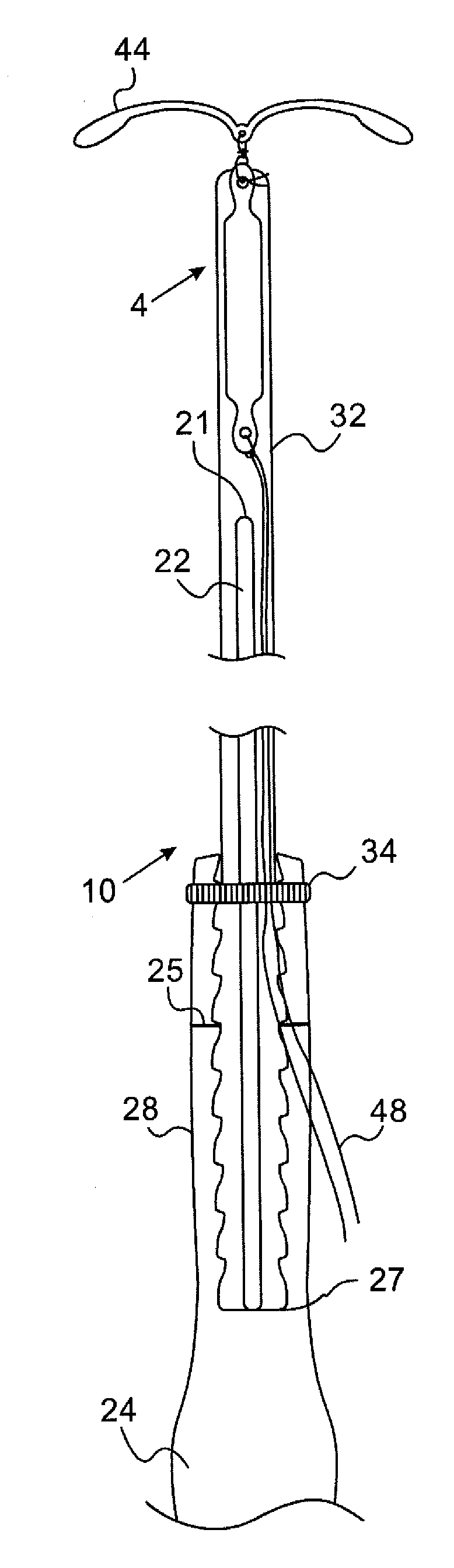
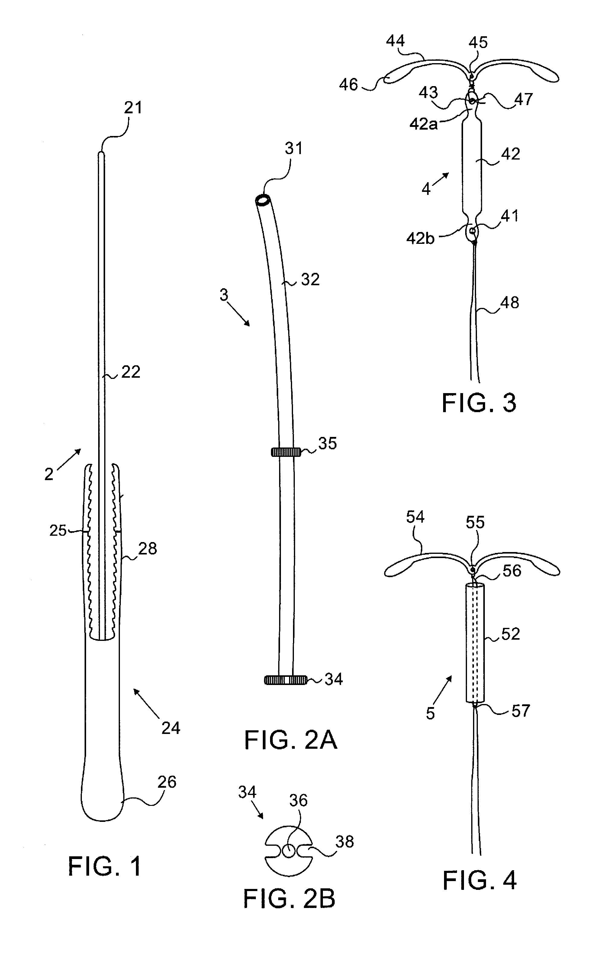
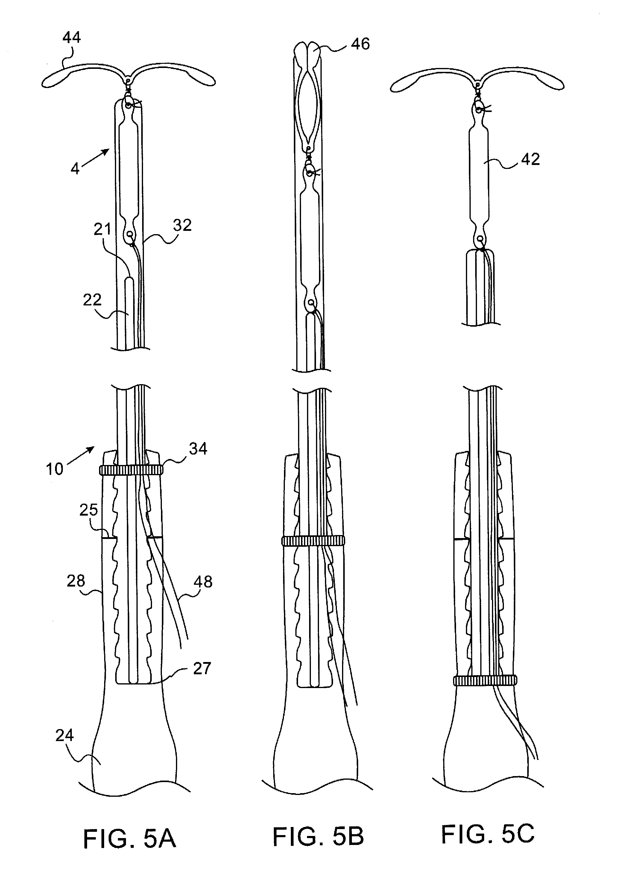
[0025]Referring to the drawings, FIGS. 1 and 2 depict the disassembled parts of an inserter for an intrauterine device in accordance with an embodiment of the invention. The assembled inserter, generally designated 10, is depicted in FIGS. 5A to 5C. Inserter 10 comprises a sleeve part 2 and a plunger part 3. Parts 2 and 3 can be easily assembled manually with no need for any tools and similarly can be easily disassembled into two separate parts to facilitate the removal of the inserter after the intrauterine device is positioned correctly inside the uterus.

[0026]Plunger part 2 comprises a thin rod 22 and a handle 24 fixedly attached to one end of the rod. Handle 24 comprises an elongated portion 26 to facilitate gripping by hand and two opposite resilient arms 28 extending upwardly in the direction of and on opposite sides of rod 22. Arms 28 are configured as tweezers arms that can bend inwardly toward each other. Rod 22 and handle 24 are preferably made from a rigid sterilizable po...


PUM


Abstract

An inserter for placing a T-shaped intrauterine device inside a patient's uterus and a T-shaped intrauterine device are disclosed. The inserter includes a sleeve part and a plunger part, the sleeve part includes a tube and a first engaging member and the plunger part includes a rod, a handle attached to the rod and a second engaging member. The first and the second engaging members are configured for reversibly engaging the sleeve part and the plunger part to temporarily lock the relative position between the tube and the rod. The T-shaped intrauterine device includes a pair of wings having a relaxed extended configuration and a contracted folded configuration and an elongated contraceptive body suspended from a junction between the wings.

Description

BACKGROUND OF THE INVENTION[0001]1. Field of the Invention[0002]The present invention generally relates to an intrauterine device (IUD) and to an inserter for placing the same. More specifically the invention relates to a combination of a one-hand-held inserter for positioning a T-shaped intrauterine device and to a T-shaped intrauterine device that are designed to make insertion easier while minimizing patient's discomfort and pain.[0003]2. Discussion of the Related Art[0004]Intrauterine devices and inserters for the same are well known. An intrauterine device (IUD) is a reversible, long acting, contraceptive device that is placed inside the uterus and can remain there for a few years. At any time that the woman plans to have a child, it can be easily removed by a clinician. Many women find the IUD to be very convenient because unlike oral contraceptives which require daily attention, an intrauterine device requires little action once it is in place.[0005]Over the years various typ...

Claims


Application Information

Patent Timeline
Patent Type & Authority Applications(United States)
IPC IPC(8): A61F6/18A61F6/14
CPCA61F6/18A61F6/144
Inventor WEITRAUB, DAVID
Owner SOROKER ERAN MR
Why Eureka
Try Eureka