Damping force controlling valve assembly for shock absorber

a technology of damping force and valve assembly, which is applied in the direction of shock absorbers, valve operating means/release devices, mechanical devices, etc., can solve the problem of limit in the magnitude of elastic modulus, and achieve the effect of reducing the damping force at low or high speed and improving the ride comfort of vehicles

Active Publication Date: 2012-05-10
HL MANDO CORP
View PDF26 Cites 5 Cited by
  • Summary
  • Abstract
  • Description
  • Claims
  • Application Information

AI Technical Summary

Benefits of technology

[0010]An aspect of the present invention is directed to a damping force controlling valve assembly, which can reduce a low or high speed damping fo...

Problems solved by technology

This results from a limitation in the magnitude of ...

Method used


Image

  • Damping force controlling valve assembly for shock absorber
  • Damping force controlling valve assembly for shock absorber
  • Damping force controlling valve assembly for shock absorber

Examples


Embodiment Construction

[0020]Exemplary embodiments of the present invention will be described below in detail with reference to the accompanying drawings. Throughout the disclosure, like reference numerals refer to like parts throughout the drawings and embodiments of the present invention.

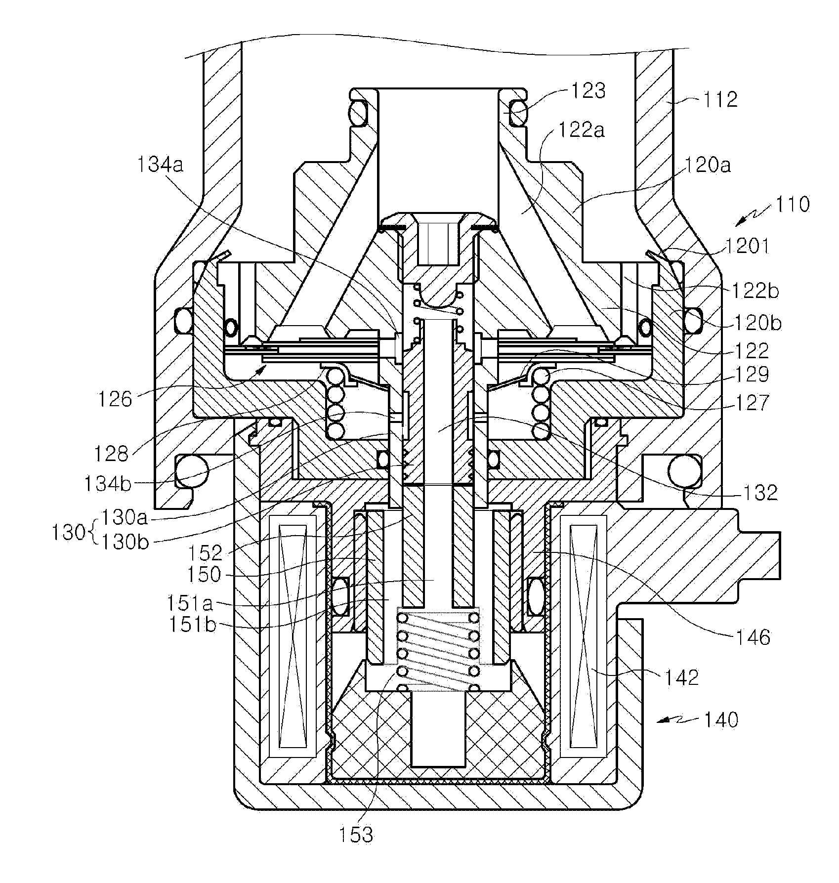
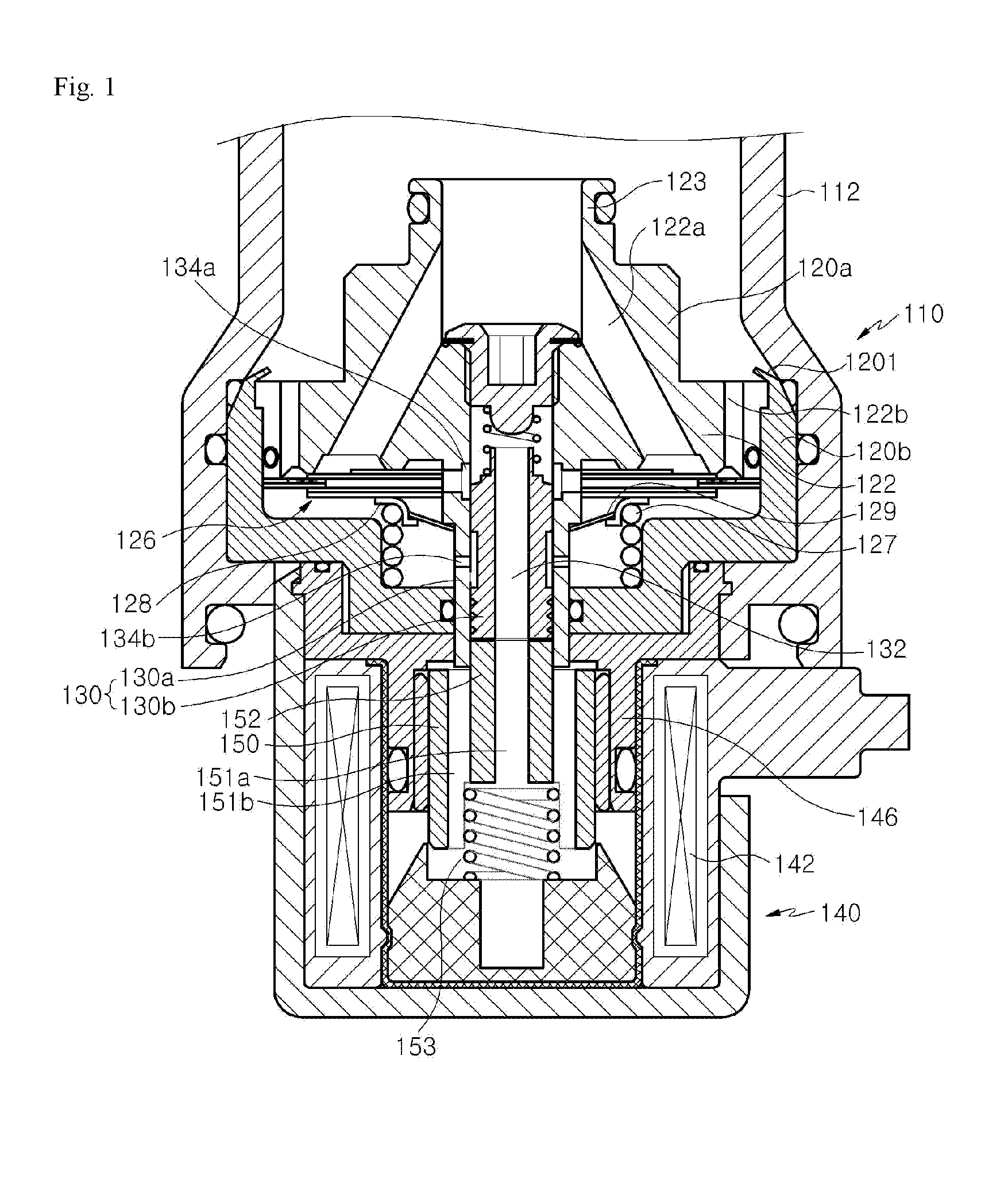
[0021]FIG. 1 is a cross-sectional view illustrating a damping force controlling valve assembly for a shock absorber according to an embodiment of the present invention.

[0022]Referring to FIG. 1, a damping force controlling valve assembly 110 is disposed at one side of a shock absorber (not shown). The shock absorber includes a cylinder and a reservoir chamber that communicates with the cylinder. A high pressure side connected to a tensioning chamber of the cylinder and a low pressure side connected to the reservoir chamber are connected to the damping force controlling valve assembly 110.

[0023]The damping force controlling valve assembly 110 includes first and second valve bodies 120a and 120b disposed inside a valve ho...


PUM


Abstract

Provided is a damping force controlling valve assembly for a shock absorber using a solenoid part for variation of a damping force. The damping force controlling valve assembly includes: a first valve body having an inlet passage through which a working fluid flows in from the shock absorber; a second valve body coupled to the first valve body with a gap therebetween; a main valve disposed at the front of a back-pressure chamber to resist the working fluid flowing through the inlet passage; and a valve spring disposed in the gap between the first valve body and the second valve body and elastically supporting the main valve.

Description

CROSS-REFERENCE(S) TO RELATED APPLICATION[0001]This application claims priority of Korean Patent Application No. 10-2010-0110557, filed on Nov. 8, 2010, in the Korean Intellectual Property Office, which is hereby incorporated by reference in its entirety.BACKGROUND OF THE INVENTION[0002]1. Field of the Invention[0003]The present invention relates to a shock absorber for a vehicle, and more particularly, to a damping force controlling valve assembly that is disposed at one side of a shock absorber to control a damping force of the shock absorber.[0004]2. Description of the Related Art[0005]Generally, a shock absorber is an apparatus that absorbs sudden shock or vibration. For example, the shock absorber is applied to a vehicle to quickly absorb vibration of a spring generated by a road surface during driving of the vehicle, to secure the driving safety and provide an improved ride comfort.[0006]During typical driving, the shock absorber reduces a damping force to absorb vibration cau...

Claims


Application Information

Patent Timeline
IPC IPC(8): F16K31/02
CPCF16F9/464
Inventor JEE, YOUNG WHAN
Owner HL MANDO CORP
Why Eureka
Try Eureka