Washing machine with improved method of braking to a non-zero speed

Active Publication Date: 2012-05-10
HAIER US APPLIANCE SOLUTIONS INC
View PDF5 Cites 8 Cited by
  • Summary
  • Abstract
  • Description
  • Claims
  • Application Information

AI Technical Summary

Benefits of technology

[0013]The present invention encompasses various method embodiments for braking a washing machine from an operational speed to a reduced non-zero speed for any reason. For example, the speed may be reduced during coast down of the basket to avoid the vibration and noise of harmonic frequencies. The speed may be reduced due to load imbalances or other abnormal or detected fault conditions. It should be appreciated that the methods are not limited to any particular type or style of washing machine, and are applicable to any washing machine that may be configured to operate as described herein. The washing machine uses a synchronous or asynchronous motor (e.g., a permanent magnet motor or an AC induction motor) for driving the machine's spin basket. Upon receipt/generation of a reduced speed signal, for e

Problems solved by technology

For example, a load imbalance during the spin cycle may require a reduced speed to prevent damage to the machine.
As the basket coasts to a stop after the spin mode, the basket may pass through one or more resonant / harmonic frequencies, generating excessive noise and vibration.
The mechanical systems that use brake pads or shoes to bring a fully loaded rotating basket to zero speed are costly to implement and maintain.
The brake shoes / pads have a limited design life and will eventually wear and need replacement.
However, as the load diminishes, the braking torque also decreases.
The dynamic and regenerative braking methods thus require braking resistors and line synchronization circuitry / hardware, which results in an increased cost per machine.
For example, the use of braking resistors impacts component sizing in the control circuit and the overall cost of such circuit.
However, DC injection braking has not been used in washing machines over the full operational loads and speeds of the machines due to the relatively large induced current spikes (and resulting thermal stresses) generated in the motor at higher loads and speeds.
Although this method utilizes DC braking over the full range of motor speeds, the system would not be particularly useful for the repeated starts and stops of a washing machine motor.
The repeated rapid and sudden charge of initial DC braking current will cause potentially damaging current spikes and significantly shorten the life of the motor and electronics in any washing machine.

Method used


Image

  • Washing machine with improved method of braking to a non-zero speed
  • Washing machine with improved method of braking to a non-zero speed
  • Washing machine with improved method of braking to a non-zero speed

Examples


Embodiment Construction

[0025]Reference now will be made in detail to embodiments of the invention, one or more examples of which are illustrated in the drawings. Each example is provided by way of explanation of the invention, not limitation of the invention. In fact, it will be apparent to those skilled in the art that various modifications and variations can be made in the present invention without departing from the scope or spirit of the invention. For instance, features illustrated or described as part of one embodiment can be used with another embodiment to yield a still further embodiment. Thus, it is intended that the present invention include such modifications and variations as come within the scope of the appended claims and their equivalents.

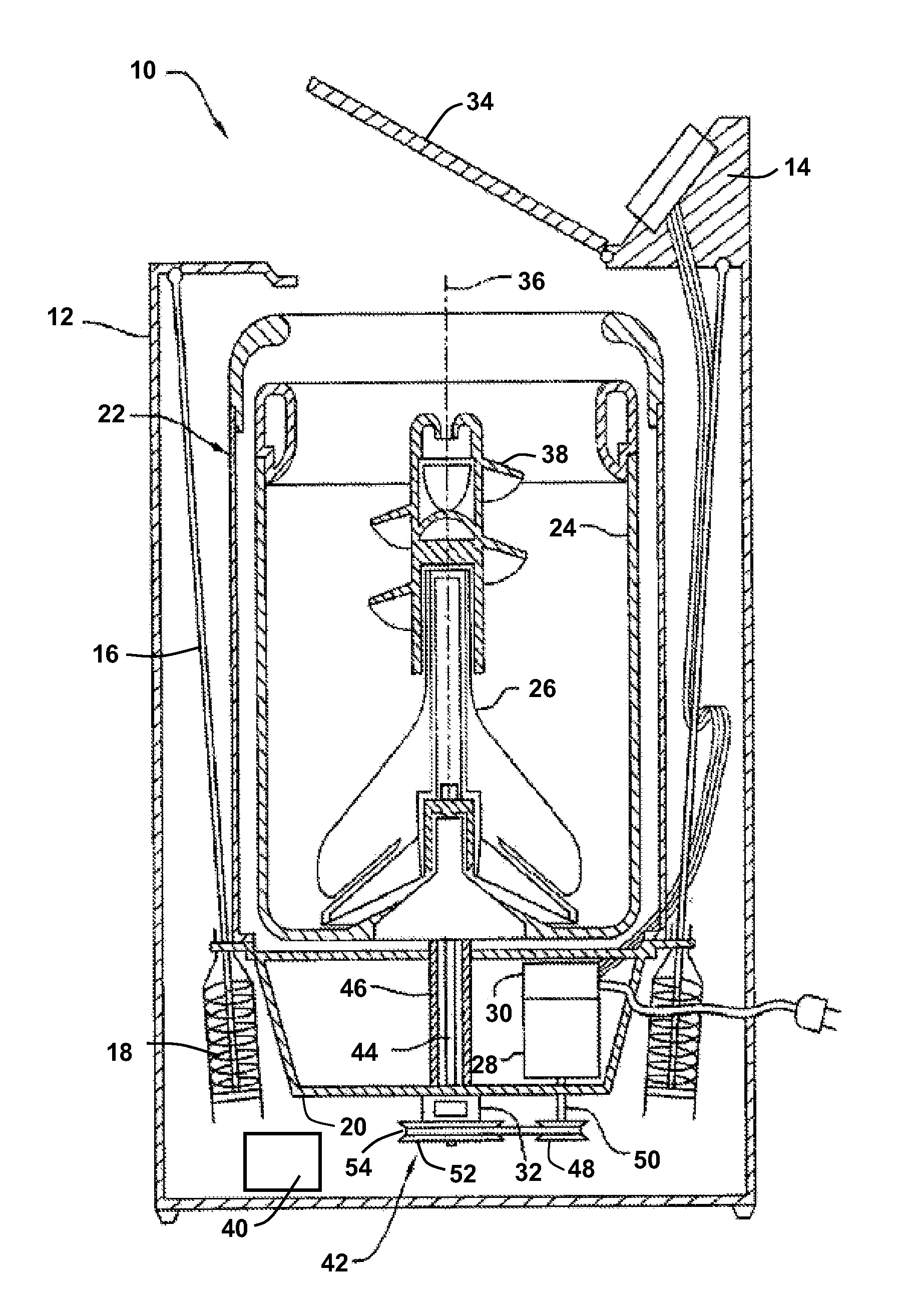
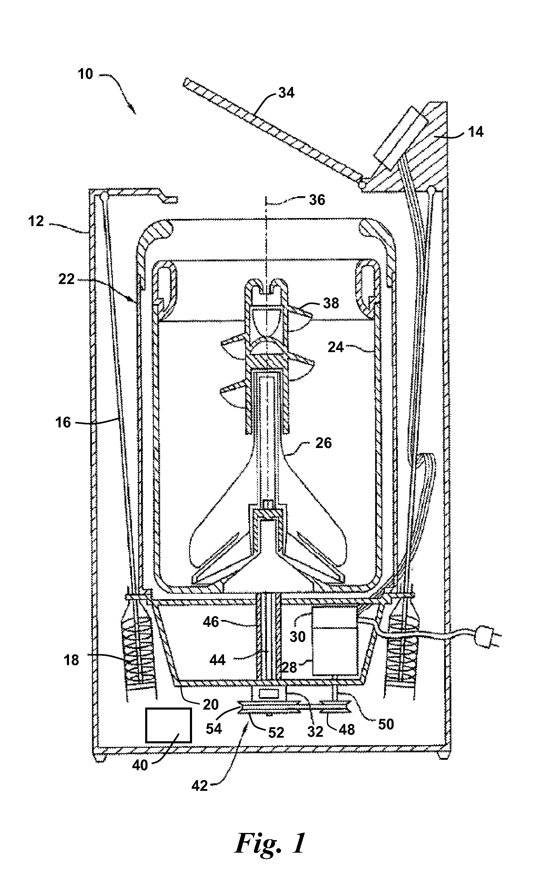
[0026]FIG. 1 depicts an exemplary washing machine 10 that may be configured in accordance with aspects of the invention. As mentioned, it should be appreciated that the particular type or style of washing machine 10 is not a limiting factor of the inventio...


PUM


Abstract

A method of braking a washing machine from an operational speed to a reduced non-zero speed is provided (as well as a washing machine incorporating the method) for a washing machine driven by one of a synchronous or asynchronous motor. Upon receipt of a speed reduction signal, the motor rotating magnetic fields are collapsed for a defined time period. After the defined time period, DC braking voltage is applied to the motor stator windings at a controlled ramp-up rate to an amplitude to generate a controlled ramped braking torque on the motor until the motor has slowed to a defined reduced speed. Thereafter, the amplitude of the DC braking voltage is set to 0V and the motor is soft started to an amplitude and reduced frequency needed to maintain the defined reduced speed.

Description

FIELD OF THE INVENTION[0001]The present invention relates generally to the field of washing machines, and more particularly to a method for braking a washing machine from an operational speed to a non-zero speed.BACKGROUND OF THE INVENTION[0002]Conventional washing machines typically include a spin basket or “tub” that holds articles (e.g., clothing) to be washed. An agitator is typically disposed within the basket, and a motor provides the drive for the basket and agitator. The motor is typically a variable speed motor (such as a variable speed AC induction motor), which is also reversible to carry out certain wash cycle functions. For example, the motor may rotate in a first direction during the agitation mode and in a second, opposite mode in the spin cycle. Other motor types have also been used in washing machines for various reasons, including permanent magnet motors such as three-phase electronically commutated (EC) motors.[0003]The typical wash cycle of a washing machine incl...

Claims


Application Information

Patent Timeline
IPC IPC(8): H02P3/24D06F33/00D06F34/08
CPCD06F33/02D06F2204/065D06F2202/065D06F37/42D06F34/08
Inventor SUEL, II, RICHARD DEAN
Owner HAIER US APPLIANCE SOLUTIONS INC
Why Eureka
Try Eureka