Speed sensor

a technology of speed sensor and sensor body, applied in the direction of magnetic measurement, measurement apparatus components, instruments, etc., can solve the problems of signal interference or signal loss, and the function cannot be guaranteed using a fixed-diameter sensor

Inactive Publication Date: 2012-05-10
CONTINENTAL TEVES AG & CO OHG
View PDF13 Cites 20 Cited by
  • Summary
  • Abstract
  • Description
  • Claims
  • Application Information

AI Technical Summary

Benefits of technology

[0008]The solution according to aspects of the invention surprisingly and simply provides a speed sensor with which the sensor housing is fixed such that it is adjustable in a simple and robust manner in the longitudinal direction and is nevertheless secure in order to avoid signal interference on account of undesirable changes in the distance between the sensor element and the encoder. The secure adjustment of the length of the wheel speed sensor also makes it possible to implement different installation situations with the sensor without having to produce a new sensor head for this purpose in each case, which may also be of interest, in particular, for small quantities.
[0009]In expedient embodiments of the speed sensor according to aspects of the invention, at least one of the following aspects can be advantageously expediently used with respect to the length adaptation and air gap adjustability:
[0018]A conical hole which forms a mating surface to the clamping ring is preferably provided in the central part of the adapter. The adapter expediently also comprises a threaded hole into which the pressure screw is screwed, which pressure screw axially loads the clamping ring and firmly braces the latter onto the sensor housing via the cone surfaces. On its outer surface, the clamping ring advantageously likewise has a cone corresponding to the cone hole in the adapter. The inner surface is designed in a manner corresponding to the sensor housing, with the result that a large clamping surface is ensured with an axial tensile stress.
[0021]Adjusting the length of the air gap or the positioning of the wheel speed sensor also makes it possible, for example, to handle different installation situations with a sensor without having to produce a new sensor head for this purpose, which may be of interest, in particular, for very small quantities. Previous adjustable wheel sensors were fixed, for example, to a displaceable fastening bushing by means of a small clamping screw, of the order of magnitude of an SW5 external hexagon. Only a length adaptation of the order of magnitude of 10 mm could also be achieved thereby.

Problems solved by technology

In installation situations in which a large number of pole pairs or teeth or a sensor wheel of small diameter, paired with large assembly tolerances, occurs, the function cannot be ensured using a sensor with fixed dimensions.
Since the sensor remains displaceable in this arrangement, there is the possibility, during driving operation, of the sensor being pushed so far out of the hole again that signal interference or signal losses can occur as a result of the changing air gap.

Method used


Image

  • Speed sensor
  • Speed sensor
  • Speed sensor

Examples


Embodiment Construction

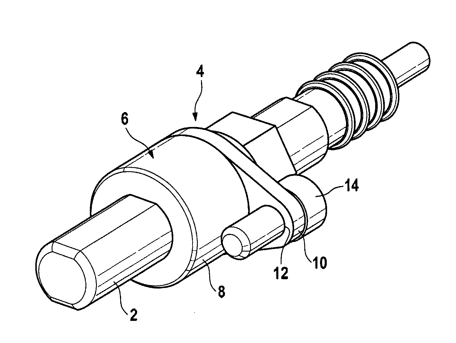
[0033]FIG. 1 shows a speed sensor housing 2 having a fastening device 4 in order to fasten the speed sensor housing to a vehicle, for example. For this purpose, provision is made of an adapter 6 which consists of a cylindrical main part 8, at one end of which a laterally protruding fastening flange 10 is provided. The fastening flange has a hole 12 through which a fastening screw 14 is inserted, which screw can be used to fasten the adapter to the vehicle, for example an axle part.

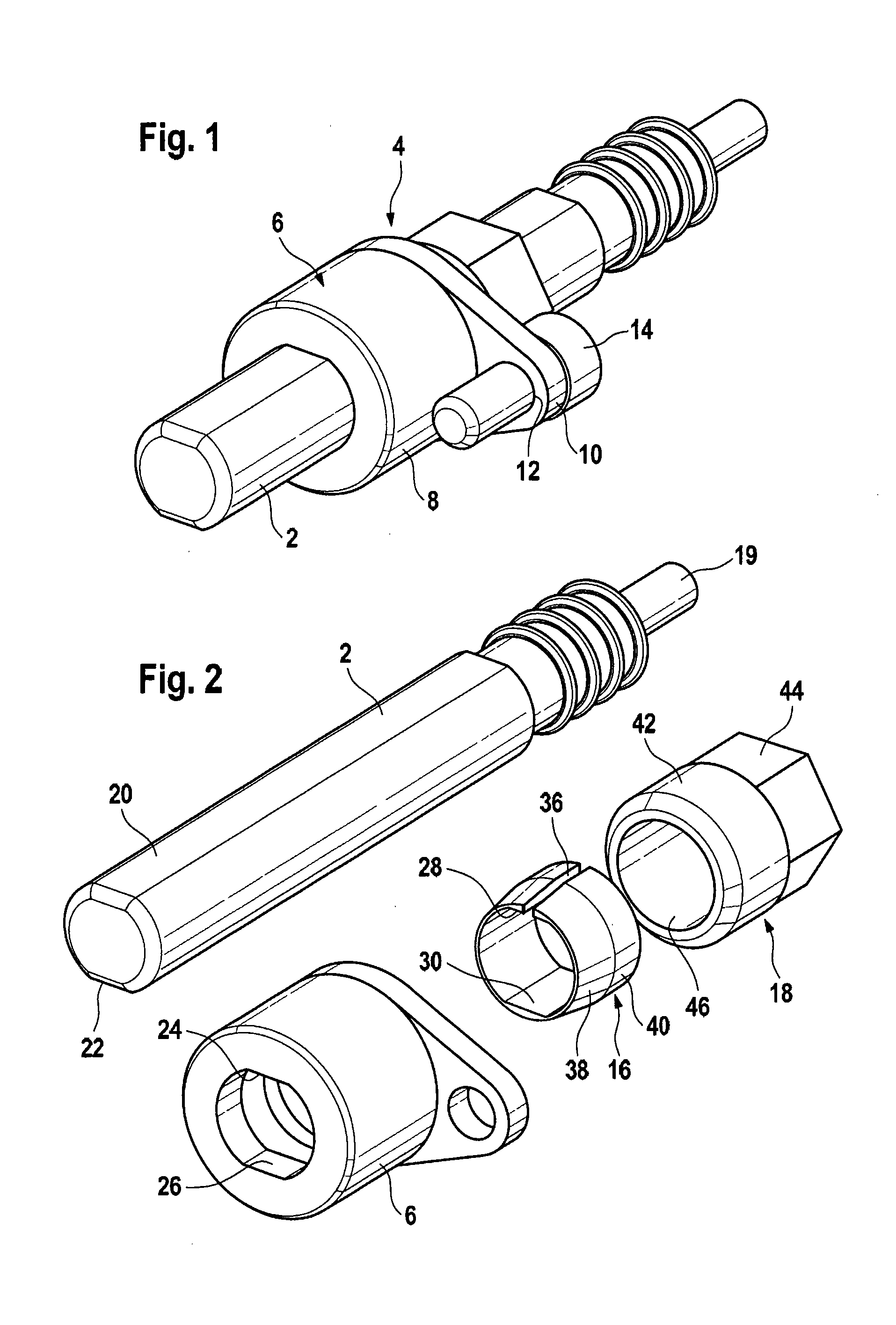
[0034]FIG. 2 illustrates individual parts of the arrangement in the dismantled state, namely the sensor housing 2, the adapter 6, a clamping ring 16 and a pressure screw 18. The sensor housing 2 is in the form of a rod and has, in its interior, a sensor element (not illustrated here) which is connected to a device for evaluating the sensor signals via a cable 19. On its outside, the sensor housing is provided with two flattened portions 20, 22 which form an antirotation safeguard with corresponding surface...


PUM


Abstract

A speed sensor having a sensor housing for accommodating a magnetic field sensor element, an adapter for holding the sensor housing and a magnetic encoder. The invention provides for the speed sensor to have a device for length adaptation or air gap adjustment, and for the device to have a clamping mechanism for holding the sensor housing.

Description

CROSS REFERENCE TO RELATED APPLICATIONS[0001]This application is the U.S. National Phase Application of PCT / EP2010 / 059355, filed Jul. 1, 2010, which claims priority to German Patent Application No. 10 2009 035 065.9, filed Jul. 28, 2009 and German Patent Application No. 10 2009 054 521.2, filed Dec. 10, 2009, the contents of such applications being incorporated by reference herein.FIELD OF THE INVENTION[0002]The invention relates to a speed sensor, in particular a wheel speed sensor having a sensor housing for accommodating a magnetic field sensor element, an adapter for holding the sensor housing and a magnetic encoder, and to the use of the speed sensor in motor vehicles.BACKGROUND OF THE INVENTION[0003]Various configurations of such speed sensors are already known. The air gap or the reading range of so-called active sensors as well is dependent on the pitch of the corresponding gearwheel or magnetic encoder. In installation situations in which a large number of pole pairs or tee...

Claims


Application Information

Patent Timeline
Patent Type & Authority Applications(United States)
IPC IPC(8): G01R33/02
CPCG01D11/245G01D11/30G01P3/488G01P1/026G01P1/00G01P1/02G01D11/24
Inventor SCHRADER, ULRICH
Owner CONTINENTAL TEVES AG & CO OHG
Why Eureka
Try Eureka