
Catheter

a catheter and catheter technology, applied in the field of catheters, can solve the problems of failure of iv failure of iv, etc., and achieve the effects of reducing the number of failed ivs, avoiding problems and risks, and reducing health care costs

Inactive Publication Date: 2012-05-10
SCHLITT MICHAEL
View PDF11 Cites 2 Cited by
  • Summary
  • Abstract
  • Description
  • Claims
  • Application Information

AI Technical Summary

Benefits of technology

[0016]It is the further goal of the present invention to provide a catheter which is capable of being incinerated and which avoids the problems and risks associated with a metallic needle or catheter.
[0017]A still further goal of the present invention is to reduce the number of failed IVs and eliminate the need for a J tube, since the needle connects directly to the catheter
[0018]A still further goal of the present invention is to reduce health care costs by reducing and hopefully eliminating the number of metal sharps used and therefore reducing the cost of safely destroying the metal sharps.

Problems solved by technology

These instruments have many disadvantages in that they are dangerous, they can be involved in the transmission of deadly diseases, such as AIDS, and the metal needles and lancets are extremely difficult to destroy thereby posing an ongoing disposal and health problem.
An additional problem with the traditional catheter lies in the fact that the metal sharp is surrounded by a plastic sheath which often causes the vein to roll out resulting in a failed IV.
These attempts to solve the needle problem have not been successful.
The plastic needles are thin and, if hard enough to puncture the skin, are too brittle and shatter.
More flexible plastic needles lack the requisite stiffness to penetrate the skin and / or vein.
Needle guards themselves have proven to be unwieldy or too costly to use or ineffective in preventing accidental punctures.

Method used


Image

  • Catheter
  • Catheter
  • Catheter

Examples


Embodiment Construction

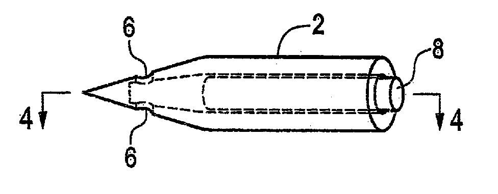
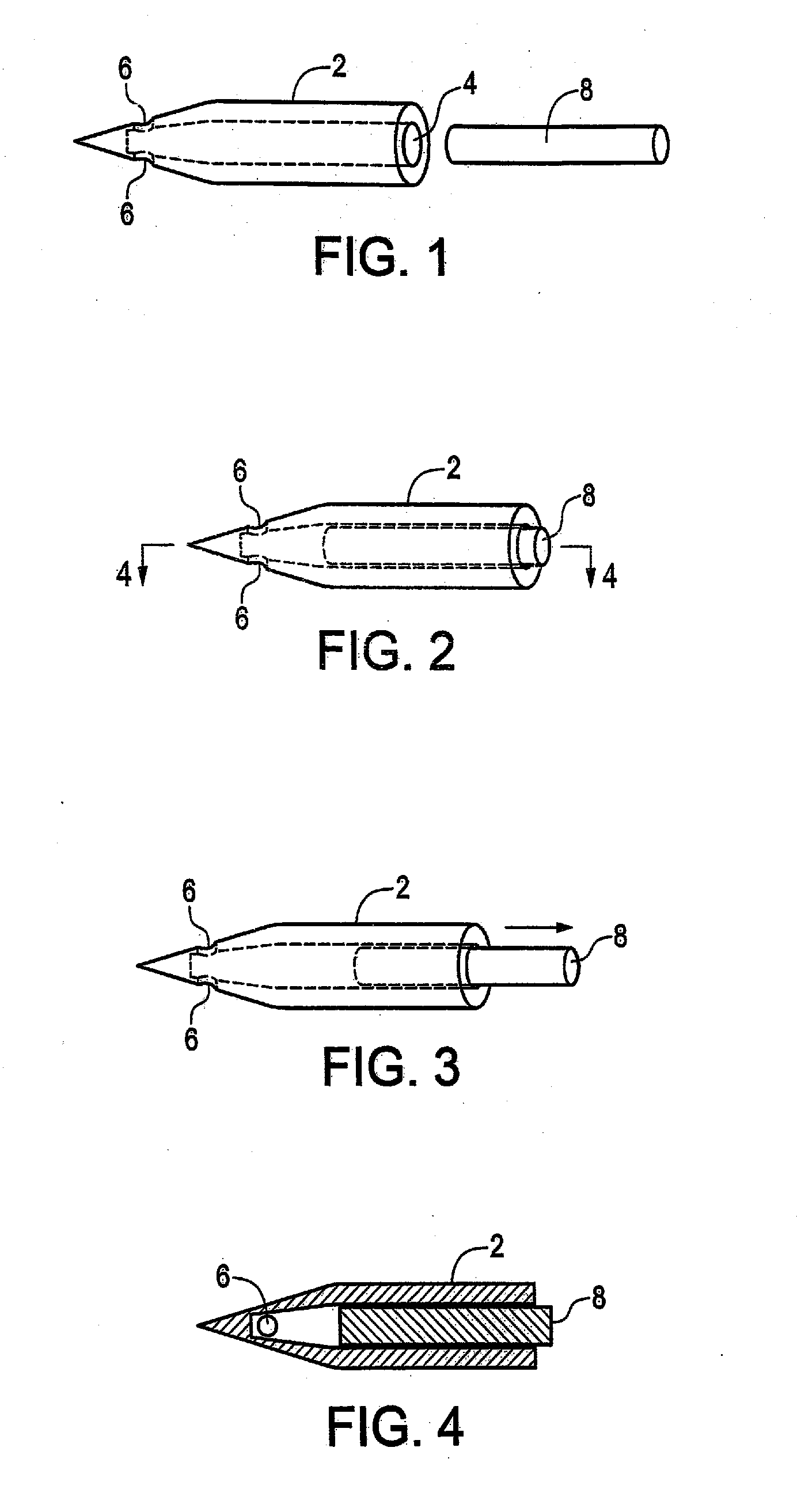
[0024]As seen in FIG. 1, the catheter comprises an outer cannula 2, including a hollow interior 4 and openings 6 adjacent the pointed skin penetrating end which extend from the exterior of the cannula 2 to the interior 4. Because it is proposed that the outer cannula be fabricated of a preferably transparent polymeric material, and being of a dimension to minimize trauma upon insertion, the inner cannula or pushrod 8 comprises a stiffening rod which closely mates with the interior bore 4 in the outer cannula 2, such that the outer cannula can be inserted through the skin and flesh and into the vein of the subject. The elimination of a sheath reduces the risk of a failed IV.

[0025]As seen in FIGS. 2 and 4, wherein the outer cannula 2 is being inserted, the pushrod 8 is adjacent and abuts the forwardmost end of the bore 4, engaging the tapered inner wall, while strengthening and making the outer cannula 2 rigid enough to penetrate the necessary material.

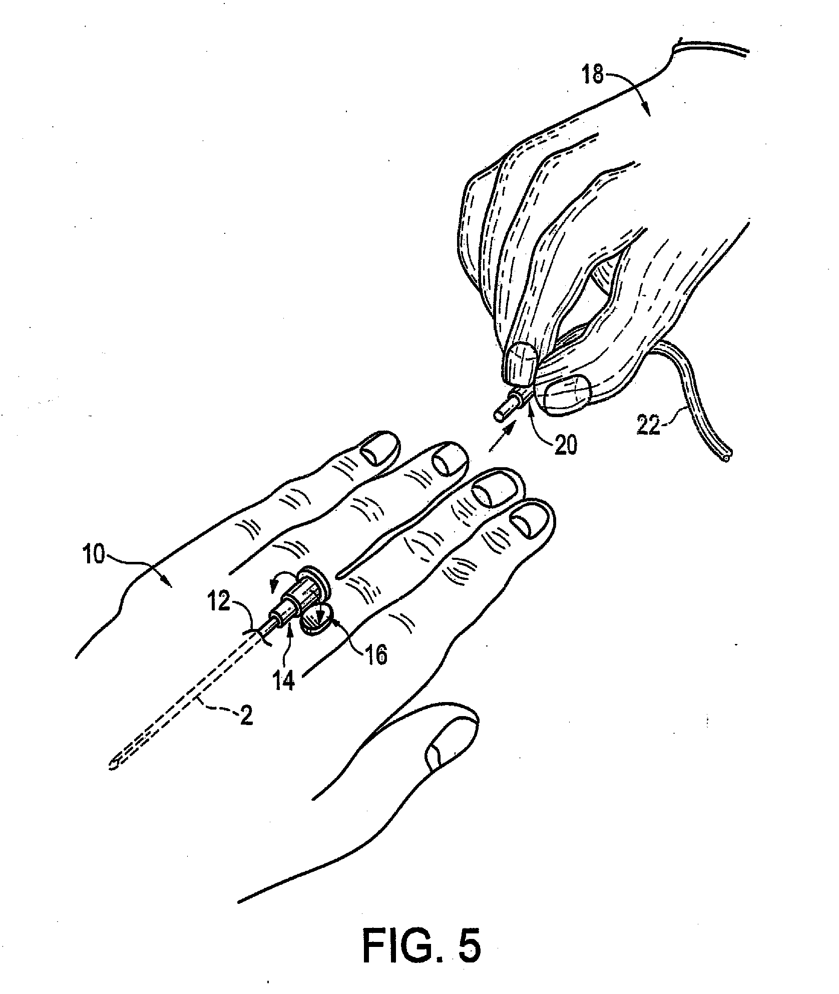
[0026]As seen in FIG. 3, the out...


PUM


Abstract

A catheter fabricated of unitary incineratable polymeric material, including a removable solid pusher rod closely mated to the interior of the cannula, engagable with the front tapered end thereof to strengthen and stiffen the cannula during insertion into the body.

Description

PRIOR APPLICATION[0001]This is a continuation-in-part application of U.S. patent application Ser. No. 12 / 632,630, filed on Dec. 7, 2009.TECHNICAL FIELD[0002]This invention relates to catheters, and more particularly to a catheter fabricated out of a unitary polymeric material capable of being incinerated, wherein the outer cannula is sharpened to facilitate penetration of the skin and blood vessel, and includes exterior bores leading to a hollow interior, wherein it is inserted into the vein and left behind having been placed by means of an inner rod, which replaces the usual cannula, which is a stiffening and pushing device which is then removed.BACKGROUND OF THE INVENTION[0003]Metal hypodermic needles and catheters have been available and have not changed in basic design in a number of years. These instruments have many disadvantages in that they are dangerous, they can be involved in the transmission of deadly diseases, such as AIDS, and the metal needles and lancets are extremel...

Claims


Application Information

Patent Timeline
Patent Type & Authority Applications(United States)
IPC IPC(8): A61M5/00
CPCA61M5/158A61M5/32A61M5/3287A61M5/329A61M25/007A61M2205/273A61M25/0102A61M25/0606A61M29/00A61M2005/3209A61M25/0082
Inventor SCHLITT, MICHAEL
Owner SCHLITT MICHAEL
Learn More