
Surgical instrument with integrated compression and distraction mechanisms

a surgical instrument and compression mechanism technology, applied in the field of spine surgery, can solve the problems of less efficiency, less accurate surgical results, and blockage of the surgical site, and achieve the effect of shortening the operating time and increasing the efficiency and accuracy of surgical steps

Inactive Publication Date: 2012-05-10
ZIMMER SPINE INC
View PDF1 Cites 18 Cited by
  • Summary
  • Abstract
  • Description
  • Claims
  • Application Information

AI Technical Summary

Benefits of technology

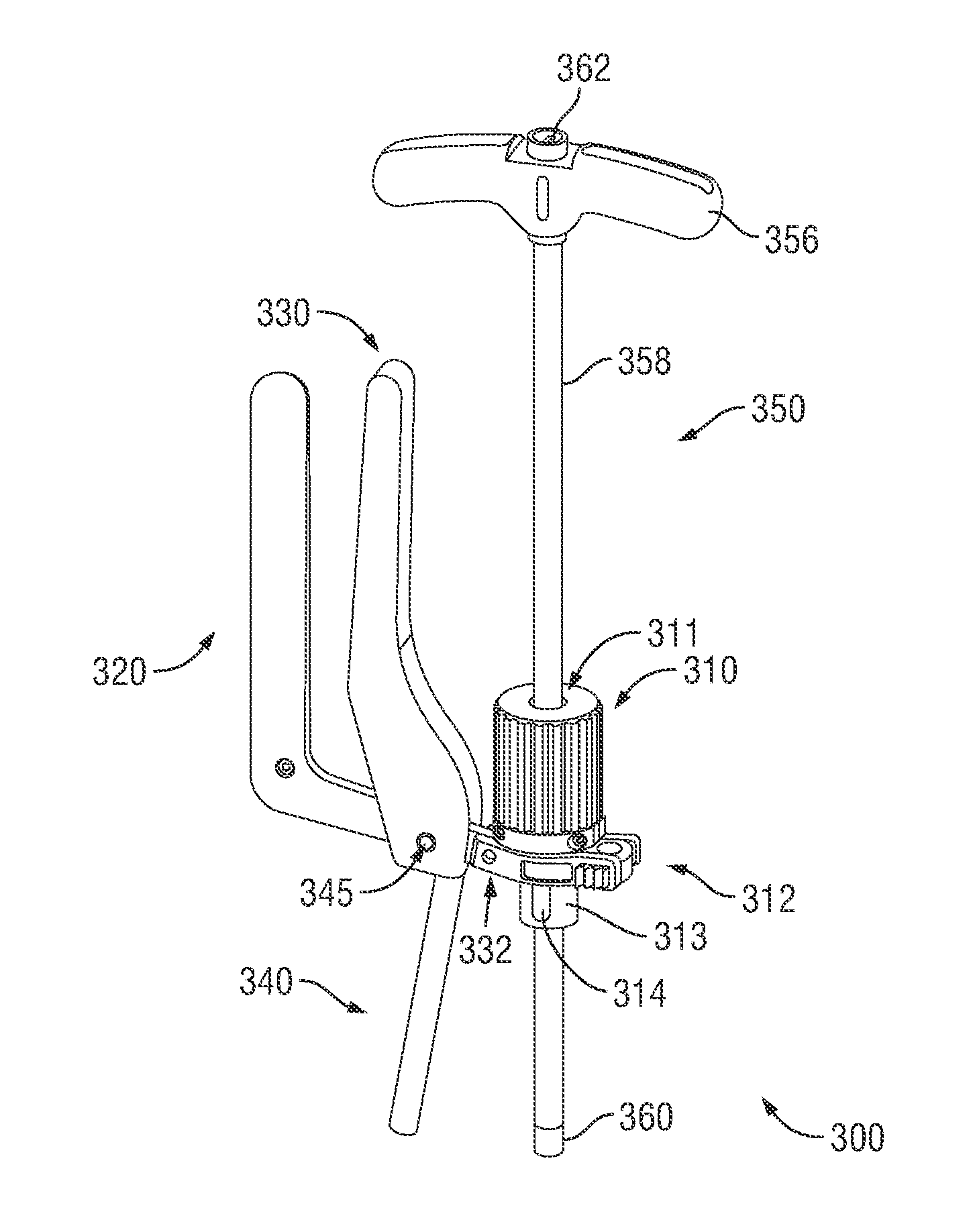
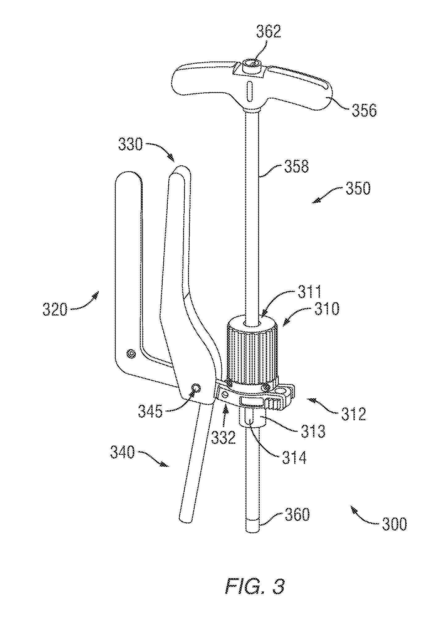
"The surgical instrument described in this patent integrates multiple surgical functions, allowing surgical personnel to compress and distract vertebrae with a single instrument. This reduces the time and complexity of the surgery and increases efficiency and accuracy. The instrument has mechanisms for compression and distraction and can be locked at different angles for different surgical procedures. It also includes a ratchet mechanism to prevent the gear mechanism from spinning and a ratchet mechanism to disengage from the gear mechanism. The method for adjusting the distance between vertebrae involves inserting the shaft of the instrument into a sleeve and locking it at a pivot angle relative to the elongated body of the instrument. The instrument can be adjusted to compress or distract the vertebrae by manipulating the distance between the bone fastener assembly and the vertebra."

Problems solved by technology

In some situations, the body of the rod reduction instrument may block the view of the surgical site.
In some scenarios, reduced visibility of the implant site can result in slower, less efficient, and less accurate surgical results than desired.
When the patient is abnormally large, the line of sight of the surgical personnel may be further impeded.
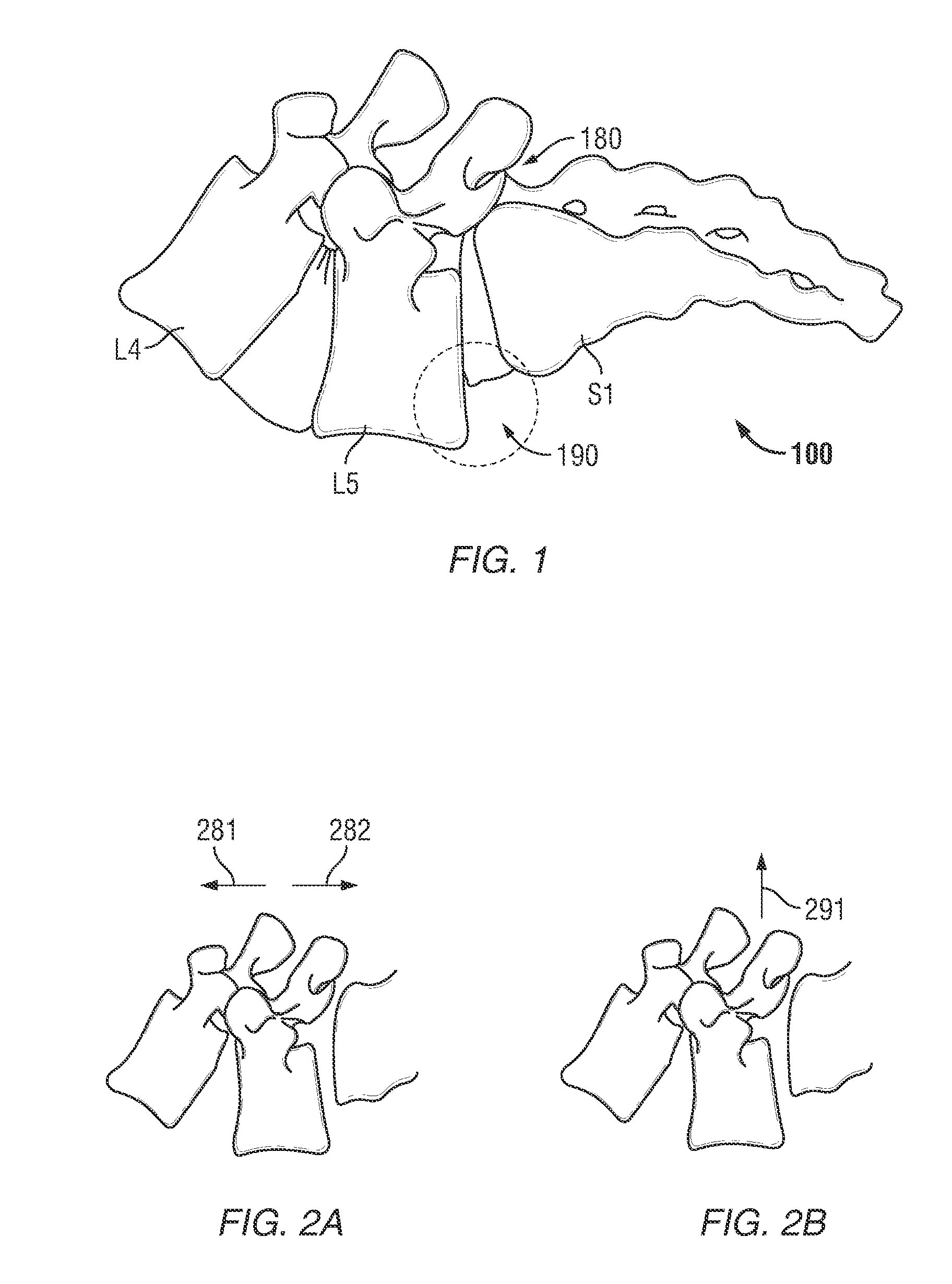
To do so, surgical personnel may use a compressor to bring the vertebrae closer to each other, use a distractor to pry them apart, or repeat the compression and the distraction steps, possibly swapping out one tool for another many times. For multi-level implants, adjusting the distance between the vertebrae can be a time consuming task.

Method used


Image

  • Surgical instrument with integrated compression and distraction mechanisms
  • Surgical instrument with integrated compression and distraction mechanisms
  • Surgical instrument with integrated compression and distraction mechanisms

Examples


Embodiment Construction

[0050]A surgical instrument with integrated compression and distraction mechanisms and the various features and advantageous details thereof are explained more fully with reference to the non-limiting embodiments detailed in the following description. Descriptions of well known starting materials, manufacturing techniques, components and equipment are omitted so as not to unnecessarily obscure the invention in detail. Skilled artisans should understand, however, that the detailed description and the specific examples, while disclosing preferred embodiments of the invention, are given by way of illustration only and not by way of limitation. Various substitutions, modifications, and additions within the scope of the underlying inventive concept(s) will become apparent to those skilled in the art after reading this disclosure. Skilled artisans can also appreciate that the drawings disclosed herein are not necessarily drawn to scale.

[0051]As used herein, the terms “comprises,”“comprisi...


PUM


Abstract

Embodiments disclosed herein provide compression / distraction methods and tools useful for fitting a spinal stabilization system in a patient through minimally invasive surgery. The spinal stabilization system may comprise screws anchored in vertebrae. The vertebrae may need to be compressed or distracted. One embodiment of an instrument disclosed herein may comprise a shaft for engaging one of the screws through an extender sleeve. A driver may engage another screw through an opening of the instrument. Through this engagement, a surgeon may use the rack and pinion of the instrument to compress or distract one or more levels of the vertebrae in a parallel motion, which can be advantageous clinically in certain situations.

Description

CROSS-REFERENCE TO RELATED APPLICATIONS[0001]This is a divisional application of U.S. patent application Ser. No. 12 / 479,445, filed Jun. 5, 2009, entitled “SURGICAL INSTRUMENT WITH INTEGRATED REDUCTION AND DISTRACTION MECHANISMS,” which is a continuation-in-part application of U.S. patent application Ser. No. 12 / 183,967, filed Jul. 31, 2008, entitled “SURGICAL INSTRUMENT WITH INTEGRATED REDUCTION AND DISTRACTION MECHANISMS.” All applications listed in this paragraph are fully incorporated herein by reference.TECHNICAL FIELD OF THE DISCLOSURE[0002]Embodiments of the disclosure relate generally to instruments for spine surgery. More particularly, embodiments of the disclosure relate to a surgical instrument with integrated compression and distraction mechanisms useful for minimally invasive spine surgery.BACKGROUND OF THE RELATED ART[0003]The spine is subject to abnormal curvature, injury, infections, tumor formation, arthritic disorders, and puncture or slippage of the cartilage disk...

Claims


Application Information

Patent Timeline
Patent Type & Authority Applications(United States)
IPC IPC(8): A61B17/56
CPCA61B17/7032A61B17/7037A61B2017/0256A61B17/708A61B17/7091A61B17/7079A61B17/60A61B17/7077A61B17/7082A61B2017/681
Inventor KING, EMILY E.RICEMAN, BRUCEFORTON, CHARLES R.MILLER, PETER THOMAS
Owner ZIMMER SPINE INC
Learn More