
Vehicle control device and rotation detection device used in same

a technology of vehicle control and detection device, which is applied in the direction of vehicle position/course/altitude control, process and machine control, instruments, etc., can solve the problems of not being able to connect the rotation detector and the standard abs control device with each other without modification, and the angle of errors tend to occur depending on objects' angles, etc., to achieve the effect of increasing the reliability of the rotation detector

Active Publication Date: 2012-05-10
NTN CORP
View PDF2 Cites 18 Cited by
  • Summary
  • Abstract
  • Description
  • Claims
  • Application Information

AI Technical Summary

Benefits of technology

[0010]In view of the foregoing, the present invention has for its essential object to provide a vehicle control device capable of accomplishing a highly reliable vehicle control with the separation distance recognized correctly, even if a reduction or an error of the detecting capability occurs in the result of measurement conducted by the separation distance measuring unit used to measure the separation distance with an object such as, for example, the inter-vehicle gap. Another important object of the present invention is to provide a rotation detector adapted for use in the vehicle control device, in which the detection resolution can be selected in dependence on the rotational speed of a rotating body of the object to be detected and the detected rotation signal can be processed even with the standard input signal resolving power, and also to provide a bearing assembly having such rotation detector incorporated therein.
[0041]In the present invention, the bearing assembly is a vehicle wheel support bearing assembly for supporting a drive wheel, in which case the use may be made of a sealing member for sealing a bearing end portion of a bearing space formed between an outer member and an inner member, the outer and inner members being rotatable relative to each other. Even in the case of this construction, an undesirable ingress of muddy water or the like from the outside can be avoided and the reliability of the rotation detector can be increased.

Problems solved by technology

It has, however, been found those prior art technologies have their own problems as discussed below.
Also, an error tends to occur depending on the angle of an object relative to the transmitting and receiving unit and / or the shape of the object.
However, since the output signal resolving power of the rotation detector and the input signal resolving power of the currently largely utilized standard ABS control device differ from each other, it is not possible to connect the rotation detector and the standard ABS control device with each other with no modification made and then to use in practice.
For this reason, the input data to the ABS control device for unitary time will become enormous particularly in a high speed rotating region and, therefore, a problem has been recognized that no processing can be accomplished with the standard ABS control device, or otherwise the processing tends to be delayed.

Method used


Image

  • Vehicle control device and rotation detection device used in same
  • Vehicle control device and rotation detection device used in same
  • Vehicle control device and rotation detection device used in same

Examples


first embodiment

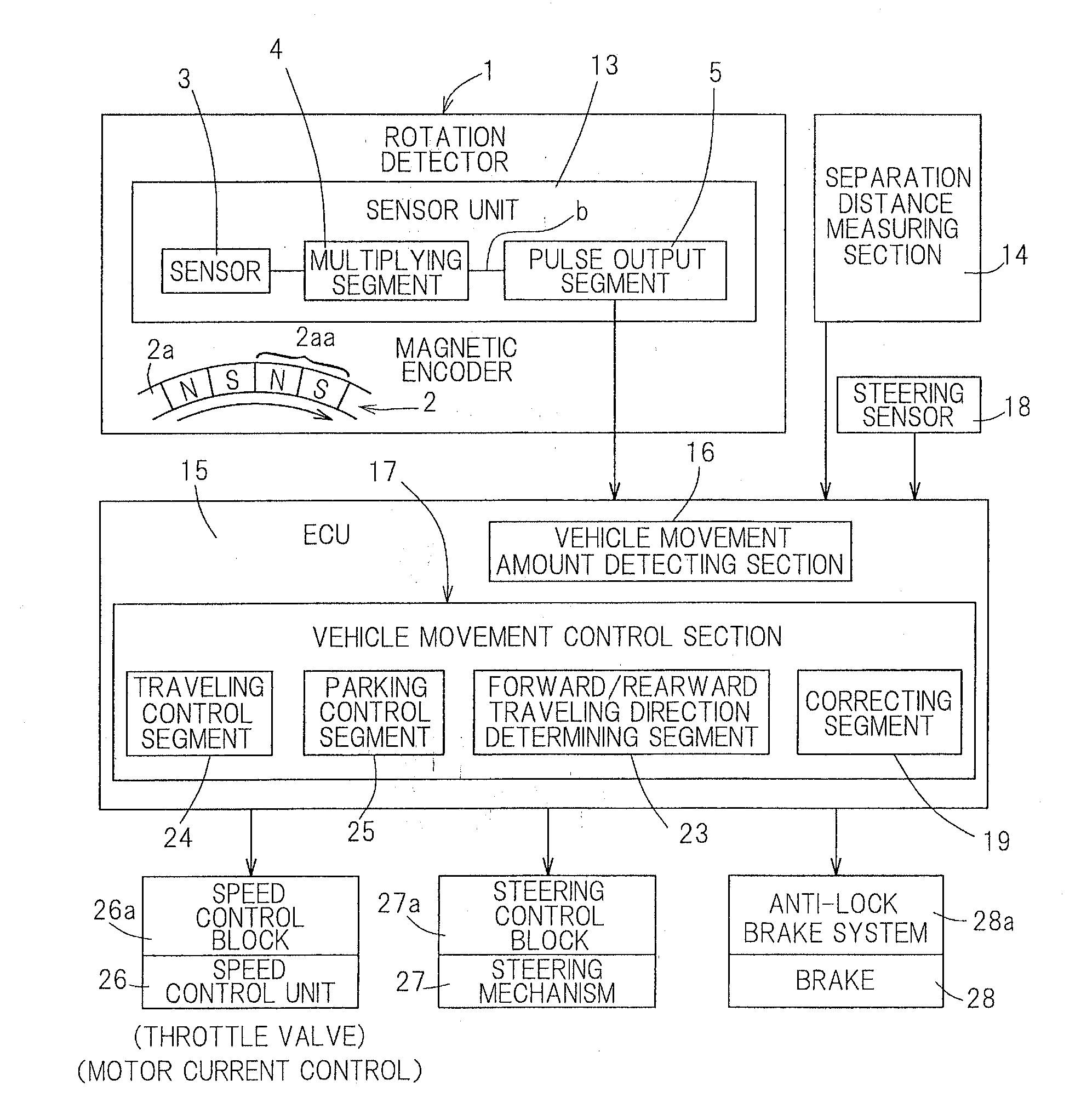
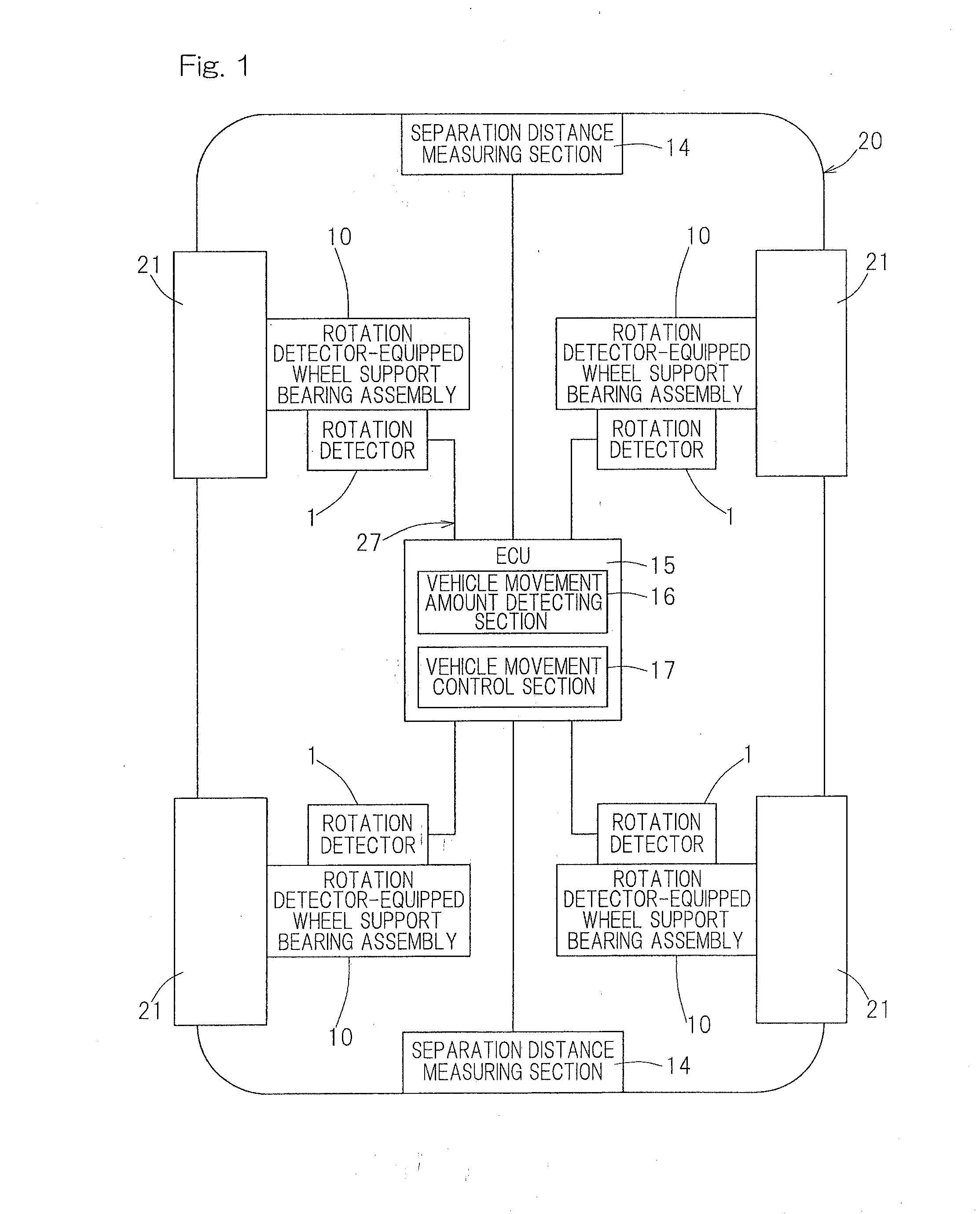
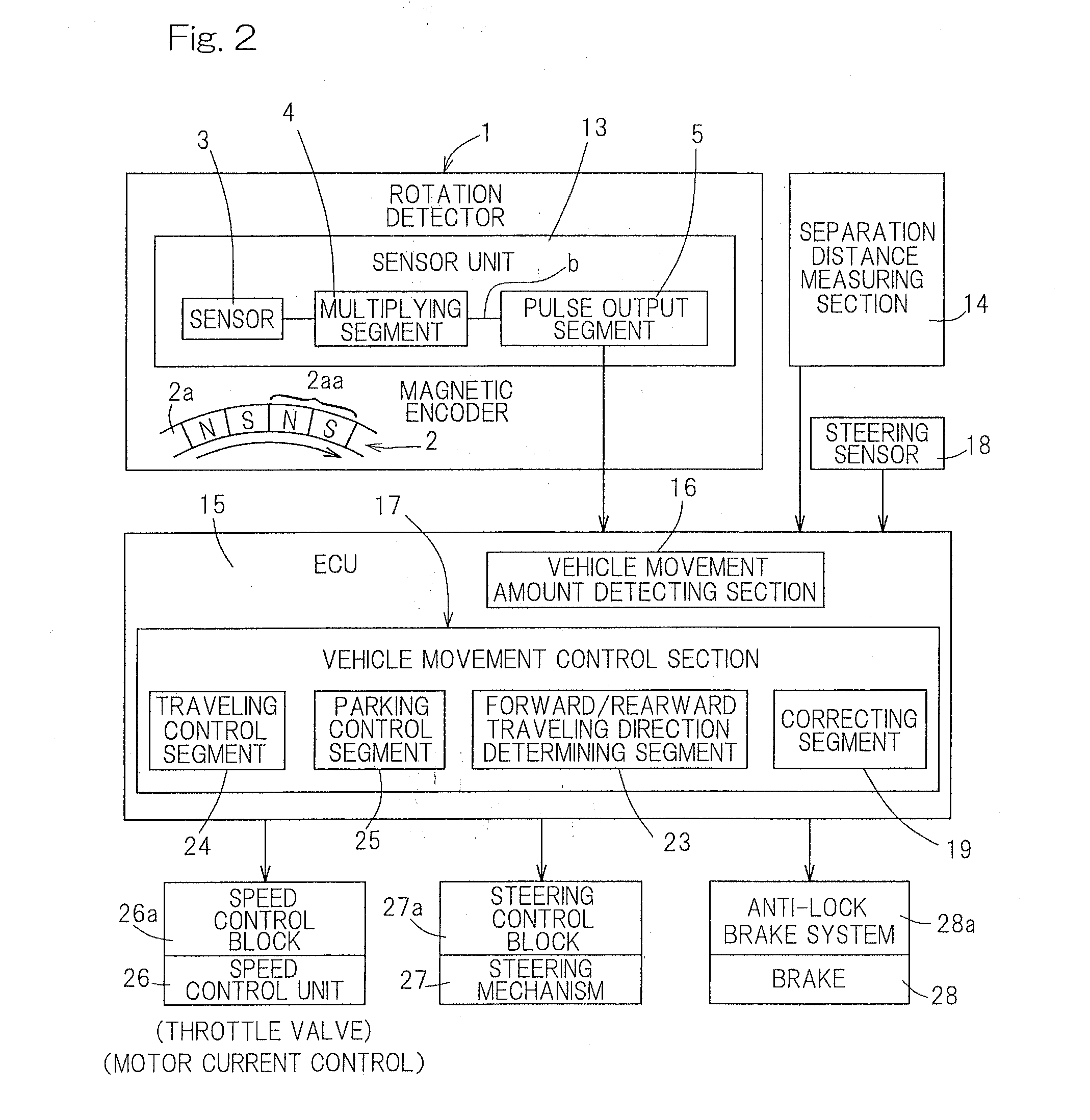
[0064]the present invention will now be described in detail with particular reference to FIGS. 1 to 8. As best shown in FIG. 1, a vehicle control device shown therein includes a rotation detector 1 for detecting the rotational speed of each of vehicle wheels 21, a vehicle movement amount detecting section 16 for detecting the amount of movement of a vehicle 20 from a signal outputted by the rotation detector 1, a separation distance measuring section 14, a separation distance measuring section 14 for measuring, on a non-contact basis, the separation distance between the vehicle 20 and an object located at a position within a region measurable from the vehicle 20, and a vehicle movement control section 17 for controlling the movement of the vehicle 20 with the utilization of the separation distance, detected by the separation distance measuring section 14, and the amount of movement of the vehicle 20 detected by the vehicle movement amount detecting section 16. The vehicle 20 referre...

fourth embodiment

[0102]With particular reference to FIGS. 12 and 13, a rotation detector equipped wheel support bearing assembly employed in the vehicle control device designed in accordance with a fourth embodiment will be described in detail. FIGS. 12 and 13 illustrates the rotation detector equipped wheel support bearing assembly similar to that shown in and described with reference to FIGS. 3 and 4, but used for the support of a vehicle driven wheel, in which the hub axle 57 has no center bore and is rendered to be solid. An outer member 51 has an inboard end extending axially beyond the inner member 52, having its end face opening covered by a cap 74. The cap 74 is mounted on and fitted to an inner periphery of the outer member 51 by means of a collar 74a provided in an outer peripheral edge. A sensor unit 13 is fitted to this cap 74 so as to confront the magnetic encoder 2. A rotation detector body is provided in the cap 74 removably with the use of bolts and nuts, both not shown, in a conditi...

fifth embodiment

[0104]With particular reference to FIGS. 14 and 15, a rotation detector equipped wheel support bearing assembly employed in the vehicle control device designed in accordance with a fifth embodiment will be described in detail. FIGS. 14 and 15 illustrate the rotation detector equipped wheel support bearing assembly similar to that shown in and described with reference to FIGS. 3 and 4, but differing therefrom in that the sealing member 61 for sealing the bearing space on the inboard side is arranged outside the magnetic encoder. In other words, the sealing member 61 comprised of a contact seal or the like is provided between an annular sensor mounting member 72, fitted to the outer member 51, and the inner ring 58. In the case of the construction described above, by the sealing member 61, the magnetic encoder 2 is sealed off from the exterior space and, hence, an undesirable biting of foreign matter between the magnetic encoder 2 and the sensor unit 13 can be avoided. The magnetic en...


PUM


Abstract

A vehicle control device capable of accomplishing a highly reliable vehicle control with the separation distance recognized correctly, even if a reduction or an error of the detecting capability occurs in the result of measurement by a separation distance measuring section for measuring the separation distance with an object such as inter-vehicle gap is provided. The control device includes a rotation detector for detecting the rotational speed of a vehicle wheel and a vehicle movement amount detecting section for detecting the amount of movement of a vehicle from an output signal thereof. The use is made of a separation distance measuring section such as a laser radar for measuring, on a non-contact basis, the separation distance between the vehicle and the object, and of a vehicle movement control section for controlling the movement of the vehicle using the separation distance and the vehicle movement amount.

Description

CROSS REFERENCE TO THE RELATED APPLICATIONS[0001]This application is a continuation application, under 35 U.S.C. §111(a), of international application No. PCT / JP2010 / 061955, filed Jul. 15, 2010, which claims priority to Japanese patent applications No. 2009-170761, filed Jul. 22, 2009, and No. 2009-176182, filed Jul. 29, 2009, the disclosure of which are incorporated by reference in their entirety into this application.BACKGROUND OF THE INVENTION[0002]1. Field of the Invention[0003]The present invention relates to a vehicle control device for performing, for example, an automatic pilot, an automatic parking, a drive assistance and a parking assistance of an automotive vehicle, to a rotation detector used in the vehicle control device, and to a rotation detector equipped bearing having the rotation detector incorporated therein.[0004]2. Description of Related Art[0005]As a measuring device for measuring the distance between two automotive vehicles, i.e., the inter-vehicle gap, and / or...

Claims


Application Information

Patent Timeline
IPC IPC(8): G05D1/02
CPCB60W30/16B60W2520/28G01D5/145G01D5/2451G01P3/489G01P3/487B60W30/09B60W30/0953G01P3/443
Inventor SHIBATA, KIYOTAKE
Owner NTN CORP
Learn More