Click to accept as built modeling

a built model and model technology, applied in the field of digital modeling, can solve the problems of requiring significant manual guesswork and manipulation, unable to use the information of the 3d model to create accurate model updates, and unable to meet the needs of users,

Active Publication Date: 2012-05-10
AUTODESK INC
View PDF7 Cites 123 Cited by
  • Summary
  • Abstract
  • Description
  • Claims
  • Application Information

AI Technical Summary

Benefits of technology

[0018]Accordingly, in one or more embodiments of the invention the communication and data exchange problems of the prior art are alleviated by providing mechanisms for both sides (i.e., digital and physical worlds) to communicate in an automatic and intuitive way. Embodiments of the invention allow non-engineering, field users to retrieve and send information for the CAD drawing via a live feed video or camera shot of the real world (the augmented reality environment). The information exchange between the real world and the technical drawing can be performed by estimating the real-world location and orientation of the camera (or camcorder) and then correlating and translating it back into the technical drawing.

Problems solved by technology

Once a plant is built, the 3D model quickly becomes stale as the built plant is modified and reconfigured as needed but the corresponding 3D model is rarely maintained.
Laser scanning to capture “as-built” information is becoming very popular but using this information to create accurate model updates requires significant manual guesswork and manipulation.
Further, prior art practices for updating digital models are very labor intensive and rely primarily on manual interpretation of as-built data by a CAD (computer aided design) operator.
Further, persons performing the actual construction / building are often not proficient with modeling programs such as a CAD or solid modeling application.
The problem with updating such designs is that the field technician cannot be expected to input the changes / modifications in the CAD application and similarly, a proficient CAD operator cannot be expected to perform the actual building / construction nor physically visit the plant to confirm the as-built state.
In summary of the above, communication between an engineer / architect or a designer / drafter that is working with digital design documents / data, and a contractor or field technician that is dealing with physical manifestation of those designs can be time-consuming, cumbersome and error-prone due to disjointed workflow that is currently followed and the heterogeneous tools / interfaces available to each role.
Translation between these two views of the world does exist, but it often introduces ambiguities and misunderstandings due to the lack of an effective multi-way communication between the two views—digital and physical.
A CAD drawing created by an engineer / designer / architect can be difficult to understand by a general contractor, and the real-world view of a general contractor cannot be easily translated back into the CAD drawing; and
A mechanical CAD drawing created by a mechanical engineer can be difficult to understand by a repair technician.
Another example of prior art limitations exists with respect to augmented reality applications.
In the prior art, expensive hardware along with sensors and markers were used to track a scene in real-time.
In view of the above, significant problems exist in the prior art with matching / synchronizing digital models to real-world projects and maintaining a two-way flow of information from digital to as-built and vice versa.

Method used


Image

  • Click to accept as built modeling
  • Click to accept as built modeling
  • Click to accept as built modeling

Examples


Embodiment Construction

[0029]In the following description, reference is made to the accompanying drawings which form a part hereof, and which is shown, by way of illustration, several embodiments of the present invention. It is understood that other embodiments may be utilized and structural changes may be made without departing from the scope of the present invention.

Overview

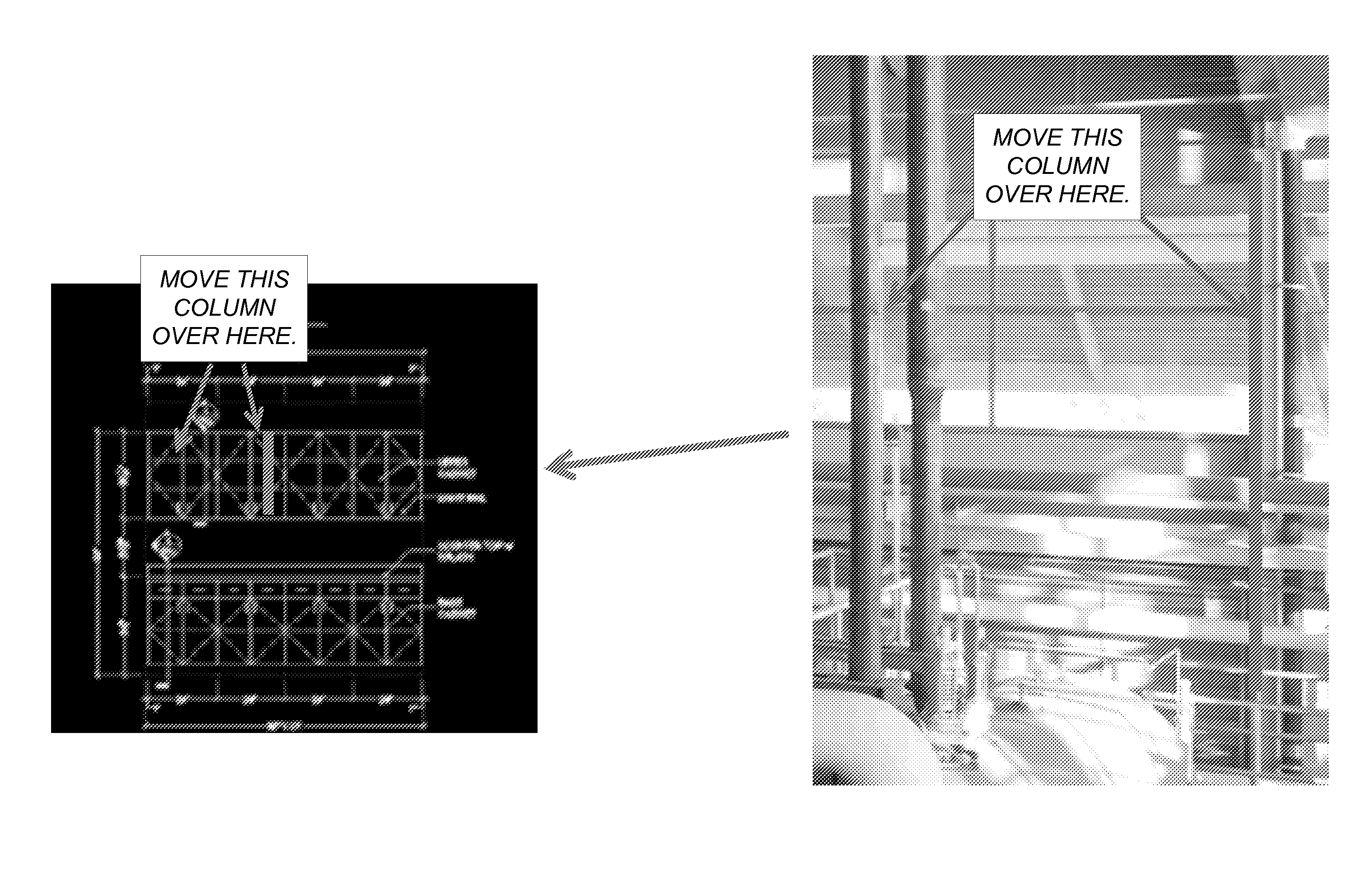
[0030]As described above, prior art techniques for updating digital models are labor and time intensive—requiring one hundred percent (100%) human manipulation of as-built data (point cloud, laser scan or image). Embodiments of the invention require zero percent (0%) human manipulation of as-built data.

[0031]Think about a very simple corollary of orienting a photograph so that up is up. Such orienting may be performed two ways: (1) The photo is presented the same way regardless of camera orientation where the photo is manually rotated (manipulated) to the right orientation; or (2) all four (4) orientations are provided and the user c...


PUM


Abstract

A method, system, apparatus, and computer program product provide the ability to augment an as-built model. A CAD drawing of a project as well as a digital representation of a physical implementation of the project are obtained. A relationship that maps the digital representation to the CAD drawing is defined / established. A component of the digital representation is identified based on the relationship (e.g., and a database / catalog). Information about the identified component is transmitted to and displayed on a computer (e.g., a mobile device).

Description

CROSS-REFERENCE TO RELATED APPLICATIONS[0001]This application claims the benefit under 35 U.S.C. Section 119(e) of the following co-pending and commonly-assigned U.S. provisional patent application(s), which is / are incorporated by reference herein:[0002]Provisional Application Ser. No. 61 / 410,795, filed on Nov. 5, 2010, by ROBERT MATTHEW SHEAR, JAMES M. AWE, BRIAN A. PENE, EDDY KUO, and KESHABA C. SAHOO, entitled “CLICK TO ACCEPT AS BUILT MODELING,” attorneys' docket number 30566.456-US-P1.BACKGROUND OF THE INVENTION[0003]1. Field of the Invention[0004]The present invention relates generally to digital modeling, and in particular, to a method, apparatus, and article of manufacture for updating and synchronizing digital models based on real world data.[0005]2. Description of the Related Art[0006]Ninety percent (90%) of plant engineering projects are done on existing “brownfield” plants. Brownfield plants are existing operating facilities that undergo continuous improvement, repair an...

Claims


Application Information

Patent Timeline
Patent Type & Authority Applications(United States)
IPC IPC(8): G06F17/50
CPCG06F17/50G06T19/006G06F17/5004G06F30/00G06F30/13
Inventor SHEAR, ROBERT MATTHEWAWE, JAMES MATSONPENE, BRIAN A.KUO, EDDYSAHOO, KESHABA CHANDRA
Owner AUTODESK INC
Why Eureka
Try Eureka