Drilling Method For Drilling A Subterranean Borehole

a subterranean borehole and drilling method technology, applied in earth drilling, wellbore/well accessories, chemistry apparatus and processes, etc., can solve the problems of not controlling the pressure/ecd along the entire wellbore length, significant pressure is required to move, and friction loss between fluid and contact surfaces

Active Publication Date: 2012-05-17
GRANT PRIDECO LP
View PDF3 Cites 21 Cited by
  • Summary
  • Abstract
  • Description
  • Claims
  • Application Information

AI Technical Summary

Benefits of technology

[0029]As a result, increasing the viscosity of the drilling fluid will increase the BHP and ECD by means of the increased frictional forces the fluid creates in the annulus as it flows through the system. Similarly, decreasing the viscosity of the drilling fluid will decrease the BHP and ECD. The increase / decrease in viscosity will also increase / decrease the point pressure along the entire well length, and so control of the viscosity of the drilling fluid also allows a user to control the pressure profile of the fluid in the annulus along the entire wellbore length.
[0031]Previously, viscosity has been used to enhance gel strengths in drilling fluids for improving cuttings suspension and cuttings carrying capacity while drilling. Gel strength is the measure of the ability of a chemical additive to be dispersed within a drilling fluid to develop and retain a gel form. The gel strength of a drilling fluid determines its ability to hold solids in suspension. It is based on its resistance to shear force, and in this case the forces acting on the drilling fluid as it flows upwards in the annulus—such as pipe rotation, and roughness factors associated with the different materials that the fluid is in contact with (drillpipe, formation, casing etc.).
[0034]Moreover, during this time, the drilling fluid becomes gel-like from the lack of the shear force from flow. The longer it remains static, the more force will be required to break the gel strength. The effects of temperature and pressure compound this. This will have a direct effect on the BHP when circulation is initiated, creating additional forces to overcome for breaking the gel strengths before drilling fluid re-commences flowing in the annulus. This will be reflected as a large increase in the BHP and is an undesired effect in drilling operations. Therefore, these effects are pronounced after connection periods when, conventionally, circulation is ceased. These can be mitigated by a continuous circulating method.
[0036]By using the method according to the invention in a continuous circulation drilling system, a new section of pipe can be added to the drillstring without having to break the gel strength of the drilling fluid and so these undesirable increases in BHP can be avoided.
[0038]The shear stress / force and shear rate are also directly proportional to the fluid velocity. Increasing the flow rate Q increases the fluid velocity which results in higher shear rates in the annulus and thus higher friction losses. Similarly, decreasing the flow rate Q decreases the fluid velocity and this results in lower shear rates in the annulus and thus lower friction losses. As a result, increasing the flow rate Q increases the BHP and ECD, and decreasing the flow rate Q decreases the BHP and ECD.
[0041]In an embodiment of the invention, the method comprises reducing the speed of rotation of the drillstring when preparing to connect a new section of drill pipe to the uppermost end of the drillstring, and simultaneously increasing the rate of flow of drilling fluid into the drillstring. Similarly, the method may comprise increasing the speed of rotation of the drillstring after having connected a new section of drill pipe to the drillstring, and simultaneously decreasing the rate of flow of drilling fluid into the drillstring.

Problems solved by technology

Friction losses create pressure losses along the fluid's flow path in the annulus, so significant pressure is required to move the mud along its flow path.
The friction losses occur between the fluid and the contact surfaces of the well bore and drill pipe.
The density and / or choke components are point pressure controls, however, and do not control the pressure / ECD along the entire wellbore length.

Method used


Image

  • Drilling Method For Drilling A Subterranean Borehole
  • Drilling Method For Drilling A Subterranean Borehole
  • Drilling Method For Drilling A Subterranean Borehole

Examples


Embodiment Construction

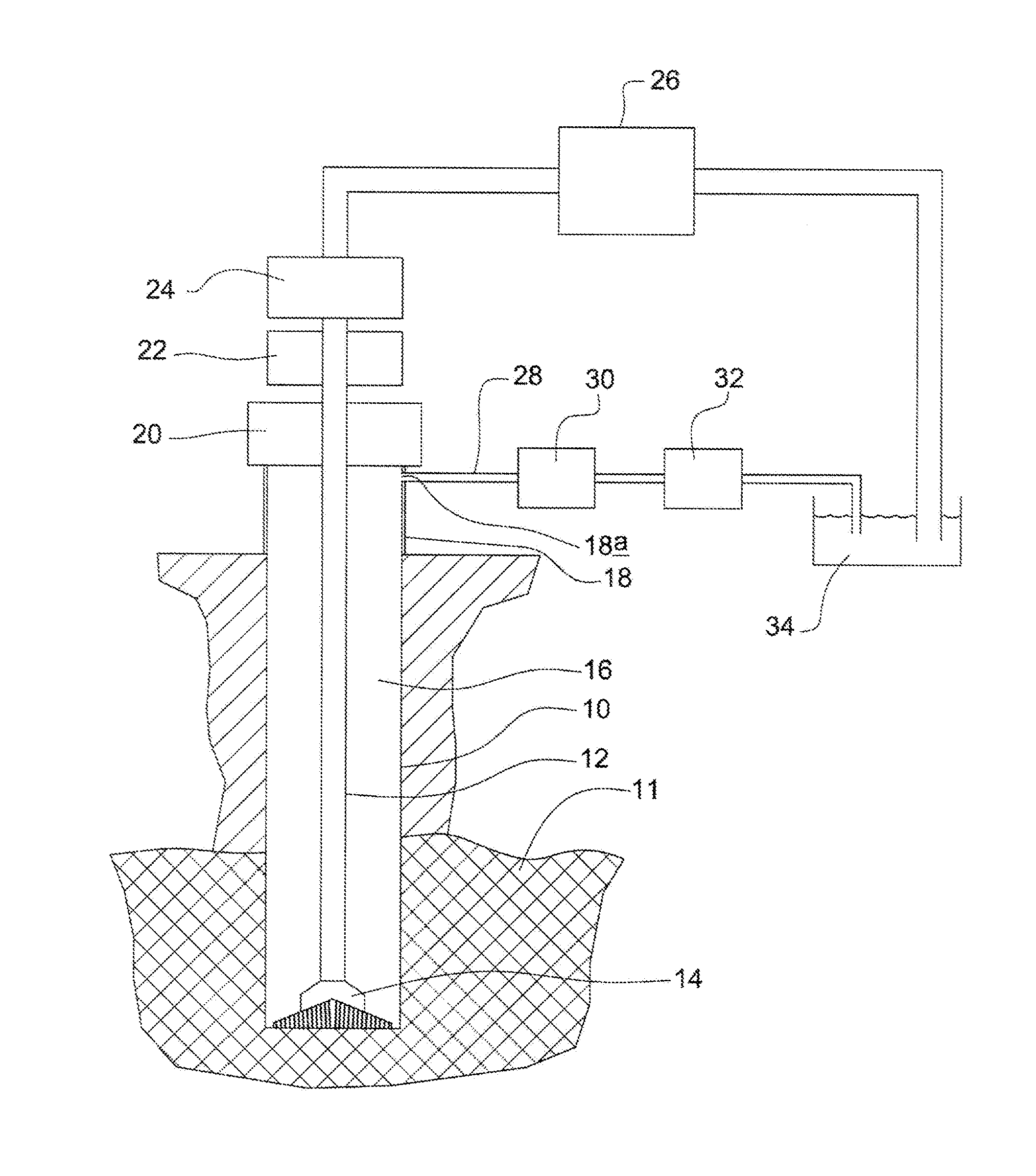
[0017]According to a first aspect of the invention we provide a method of drilling a subterranean borehole comprising:[0018]a) pumping a drilling fluid into an uppermost end of a drillstring, the drillstring having a bit at an end thereof,[0019]b) rotating the drillstring about its longitudinal axis so that the bit forms a borehole in the ground,

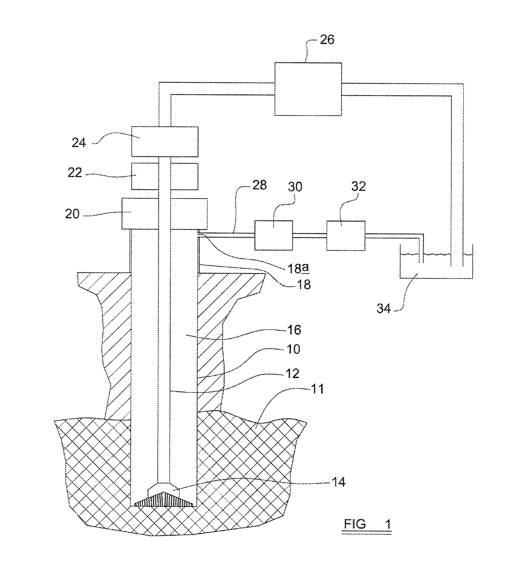
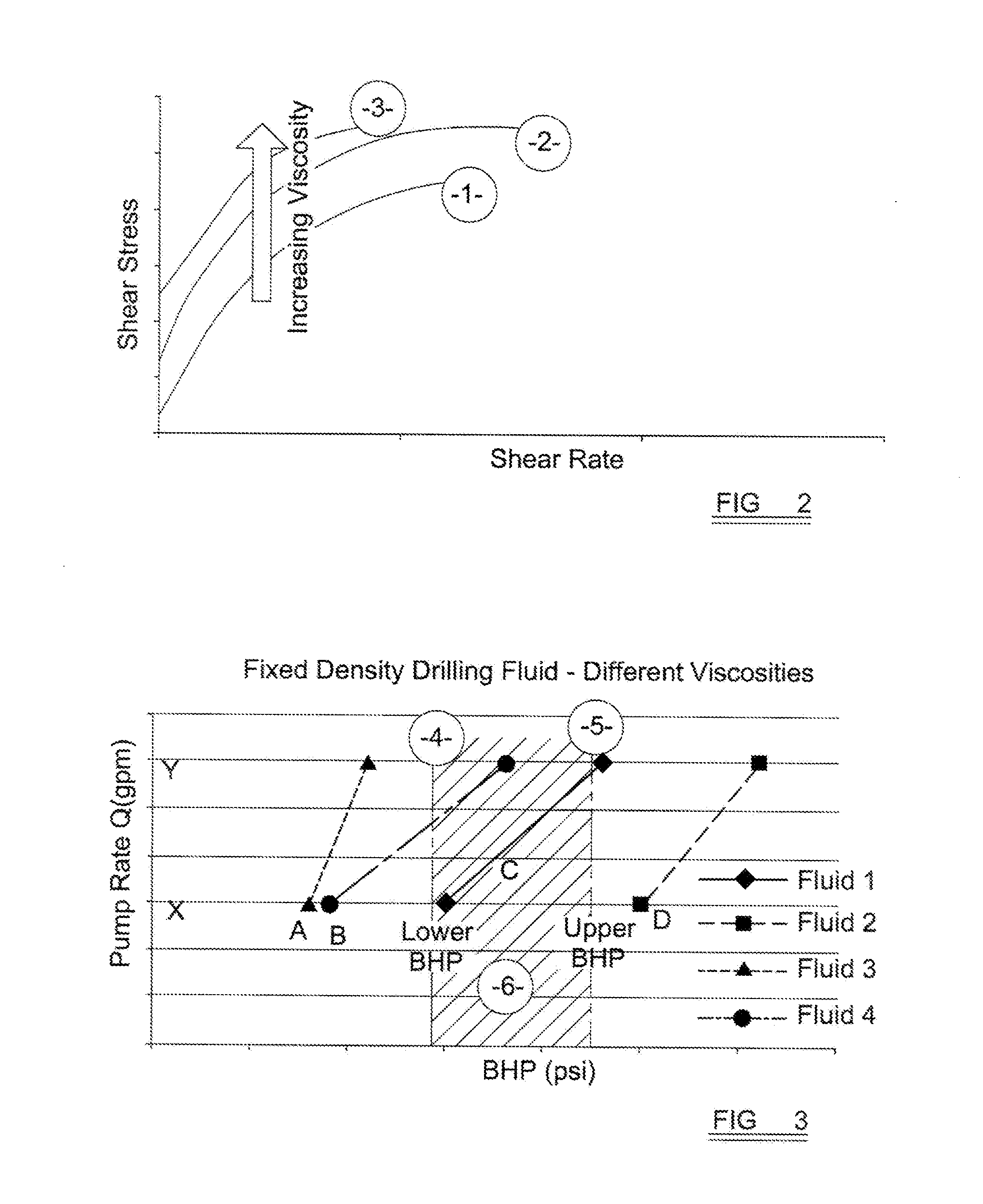
the method further comprising the steps of:[0020]c) determining a desired drilling fluid flow rate range[0021]d) determining the desired upper and lower limits of the fluid pressure at the bottom of the wellbore (the BHP);[0022]e) determining the viscosity of drilling fluid which will maintain the BHP within the range set by the upper and lower BHP limits over the entire or the majority of the required drilling flow rate range;[0023]f) adjusting the composition of a drilling fluid to bring the drilling fluid to the viscosity calculated in step e above.

[0024]Steps c, d, e and f may be carried out prior to steps a and b (i.e. before drilling h...


PUM


Abstract

A method of drilling a subterranean borehole comprising:a) pumping a drilling fluid down a drillstring (12), the drillstring (12) having a bit (14) at an end thereof,b) rotating the drillstring (12) about its longitudinal axis so that the bit forms a borehole (10) in the ground,the method further comprising the steps of:c) determining a desired drilling fluid flow rate ranged) determining the desired upper and lower limits of the fluid pressure at the bottom of the wellbore (the BHP);e) determining the viscosity of drilling fluid which will maintain the BHP within the range set by the upper and lower BHP limits over the entire or the majority of the required drilling flow rate range;f) adjusting the composition of a drilling fluid to bring the drilling fluid to the viscosity calculated in step e above.

Description

RELATED APPLICATIONS[0001]This application claims priority to U.S. Provisional Patent Application Ser. No. 61 / 414,248 filed on Nov. 16, 2010, which is incorporated by reference in its entirety.FIELD OF THE INVENTION [0002]The present invention relates to a method of drilling a subterranean borehole.Description of the Prior Art and Background to the Invention[0003]Subterranean drilling of a bore hole or wellbore typically involves rotating a drill bit from surface or on a downhole motor at the remote end of a tubular drill string. It involves pumping a fluid down the inside of the tubular drillstring, through the drill bit, and circulating this fluid continuously back to surface via the drilled space between the hole / tubular, referred to as the annulus. This pumping mechanism is provided by positive displacement pumps that are connected to a manifold which connects to the drillstring, and the rate of flow into the drillstring depends on the speed of these pumps. The drillstring is co...

Claims


Application Information

Patent Timeline
Patent Type & Authority Applications(United States)
IPC IPC(8): E21B21/08
CPCE21B21/08E21B44/04E21B44/00
Inventor ORBELL, CHARLESSAVAGE, PAT
Owner GRANT PRIDECO LP
Why Eureka
Try Eureka