
Gravity and Buoyancy Electricity Generation System

a technology of buoyancy and electricity generation system, applied in the direction of mechanical energy handling, mechanical equipment, machines/engines, etc., can solve the problems of inexhaustible and abundant gravity and buoyancy

Inactive Publication Date: 2012-05-17
SPARKS USHIJIMA SHIRO CRESTO
View PDF14 Cites 11 Cited by
  • Summary
  • Abstract
  • Description
  • Claims
  • Application Information

AI Technical Summary

Benefits of technology

"The present invention is an electricity generating system that uses two principles of nature, gravity and buoyancy, to generate clean energy on a large scale. The system is environmentally friendly, as it does not emit any emissions and is in constant availability. It can be located anywhere in the world, as the two principles are found naturally and abundantly. The amount of energy generated can be increased or decreased based on the size of the structure, and the system can be controlled and managed. The system is cost-effective, as there is no need for expensive raw materials to produce energy. It is also reliable, as it can produce energy even when there is no sun or wind. The system can be used to drive generators and produce energy in a sustainable and eco-friendly way."

Problems solved by technology

Abundant—The two principles used in this system i.e. gravity and buoyancy are abundant and practically inexhaustible.

Method used


Image

  • Gravity and Buoyancy Electricity Generation System
  • Gravity and Buoyancy Electricity Generation System
  • Gravity and Buoyancy Electricity Generation System

Examples


Embodiment Construction

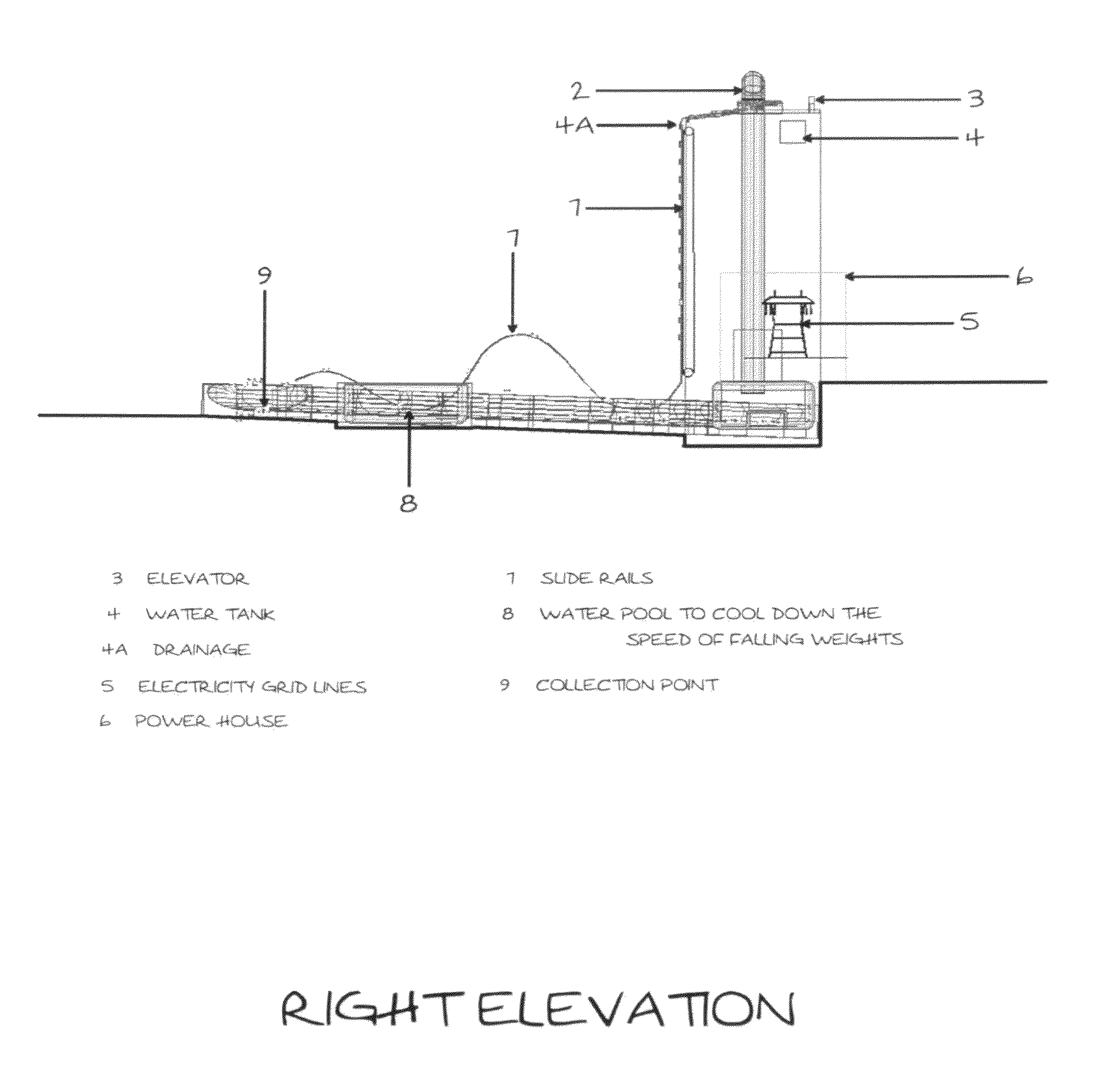
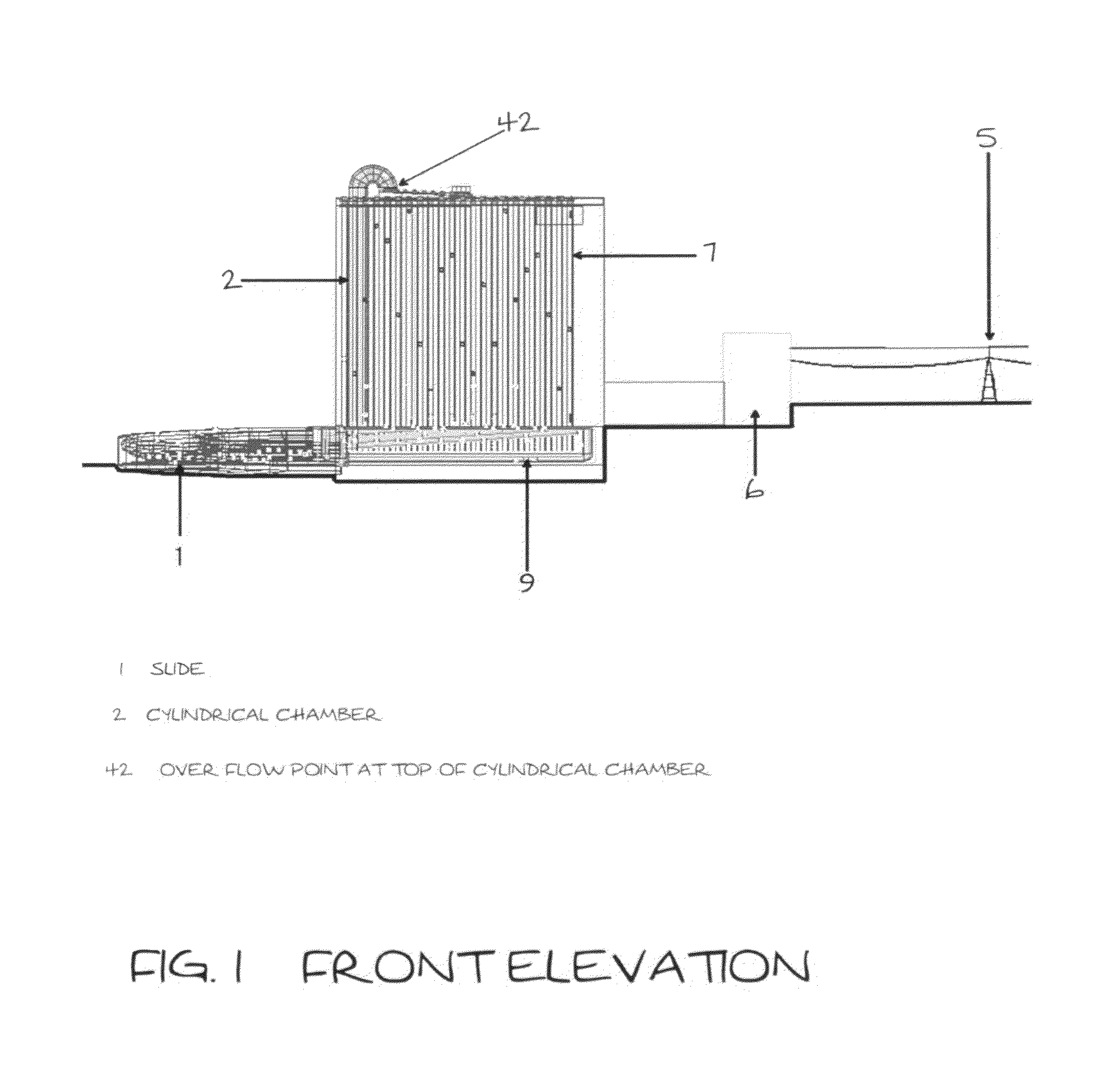
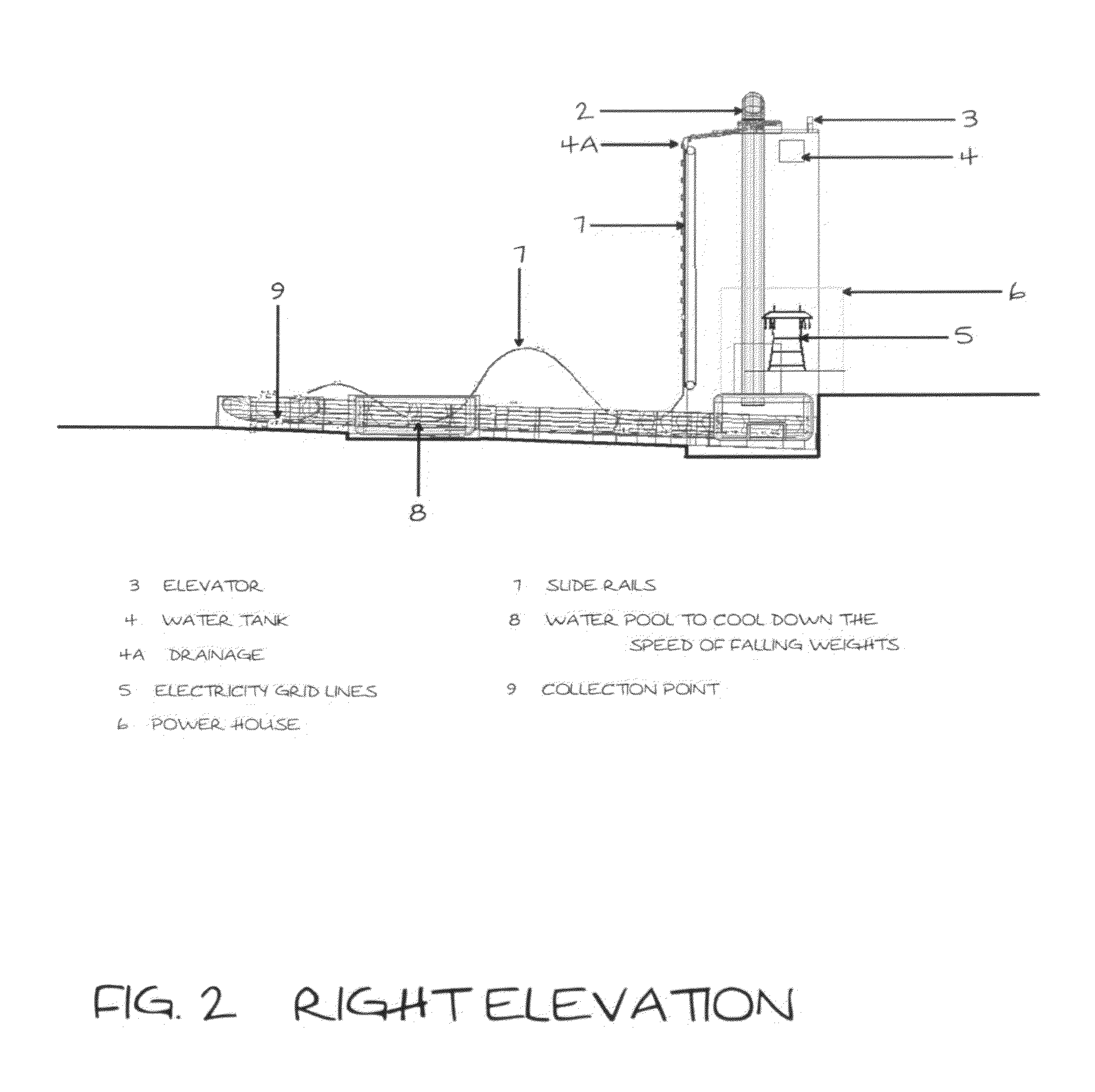
[0061]FIG. 1 shows the front elevation of the whole structure. 2 shows the cylindrical chamber which is filled with water. It is in this unit that the weights float to the top of the structure and are moved out by water overflowing from the top of the cylinder. The water is then drained at point 4A on FIG. 2 to a water tank 4 in FIG. 2. This water is pumped back to the top of the cylindrical chamber (2) to keep the water overflowing by a pump located near the water tank at 4 on FIG. 2.

[0062]The weights then slide down and are arranged and set at different drop off points at the edge of the structure, where they are let free to drop down due to the force of gravity.

[0063]The weights drop down freely, but are guided in direction by slide rails as seen in 7 on FIG. 3.

[0064]They then reach the bottom and the velocity is (optionally) cooled off by driving them up a height and into a water pool as seen at 8 or by trapping the motion using similar motors as shown in FIG. 21 but this time a...


PUM


Abstract

A method of generating electricity for mass production using the principles of gravity and buoyancy, that is:Abundant, Environmentally friendly, Clean, Controlled and manageable, Geographically applicable, Cheap and Reliable.

Description

REFERENCES CITEDU.S Patent Documents[0001]1,708,807April 1929F. Tatay2,037,973April 1936A. G. Grondahl2,135,110Nov. 1, 1938Platt3,857,242Dec. 31, 1974Gilmore3,934,964Jan. 27, 1976Diamond4,054,031Oct. 18, 1977Johnson4,498,294Feb. 12, 1985Everett4,538,415Sep. 3, 1985Lebecque4,715,182Dec. 29, 1987Adams5,753,978May 19, 1998Lee5,905,312May 18, 1999Liou5,944,480Aug. 31, 1999Forrest6,009,707Jan. 4, 2000Alkhamis6,249,057 B1Jun. 19, 2001Lehet6,305,165 B1Oct. 23, 2001Mizuki6,734,574 B2May 11, 2004Shin6,817,180 B2Nov. 16, 2004Newman6,978,610 B2Dec. 27, 2005Carnahan7,134,283 B2Nov. 14, 2006VillalobosFIELD OF THE INVENTION[0002]The present invention relates generally to an electricity generating apparatus and more specifically to a gravity-buoyancy energy system. The present invention utilizes principles of buoyancy to lift weights to selected height for subsequent use in gravitationally driving an energy generator.BACKGROUND OF THE INVENTION[0003]With today's increased energy needs of society, ...

Claims


Application Information

Patent Timeline
Patent Type & Authority Applications(United States)
IPC IPC(8): H02K7/18F03B17/04
CPCF03B17/04Y02E10/20H02K53/00
Inventor SPARKS, USHIJIMA SHIRO CRESTO
Owner SPARKS USHIJIMA SHIRO CRESTO
Learn More