Charge state detection circuit, battery power supply device, and battery information monitoring device

Inactive Publication Date: 2012-05-17
PANASONIC CORP
View PDF2 Cites 39 Cited by
  • Summary
  • Abstract
  • Description
  • Claims
  • Application Information

AI Technical Summary

Benefits of technology

[0011]An object of this invention is to provide a charge state detection circuit which can ascertain the state of charge of a battery block even when a portion of the secondary batteries i

Problems solved by technology

In such a battery power supply device, when an overcurrent, overheating, or another abnormality occurs in a portion of the secondary batteries in a battery block, if charging and discharging of the battery block are performed in the same manner as usual, there is the concern that the secondary batteries may be caused to degrade.
However, when an abnormality occurs in a portion of the secondary batteries included in a battery block as in the above-described techniques, there are cases in which prohibiting charging and discharging of the entire battery power supply device is undesirable.
Hence in applications such as HEVs, if charging/discharging of a battery power supply device is prohibited when an abnormality occurs in a portion of the secondary batteries included in a battery

Method used


Image

  • Charge state detection circuit, battery power supply device, and battery information monitoring device
  • Charge state detection circuit, battery power supply device, and battery information monitoring device
  • Charge state detection circuit, battery power supply device, and battery information monitoring device

Examples


first embodiment

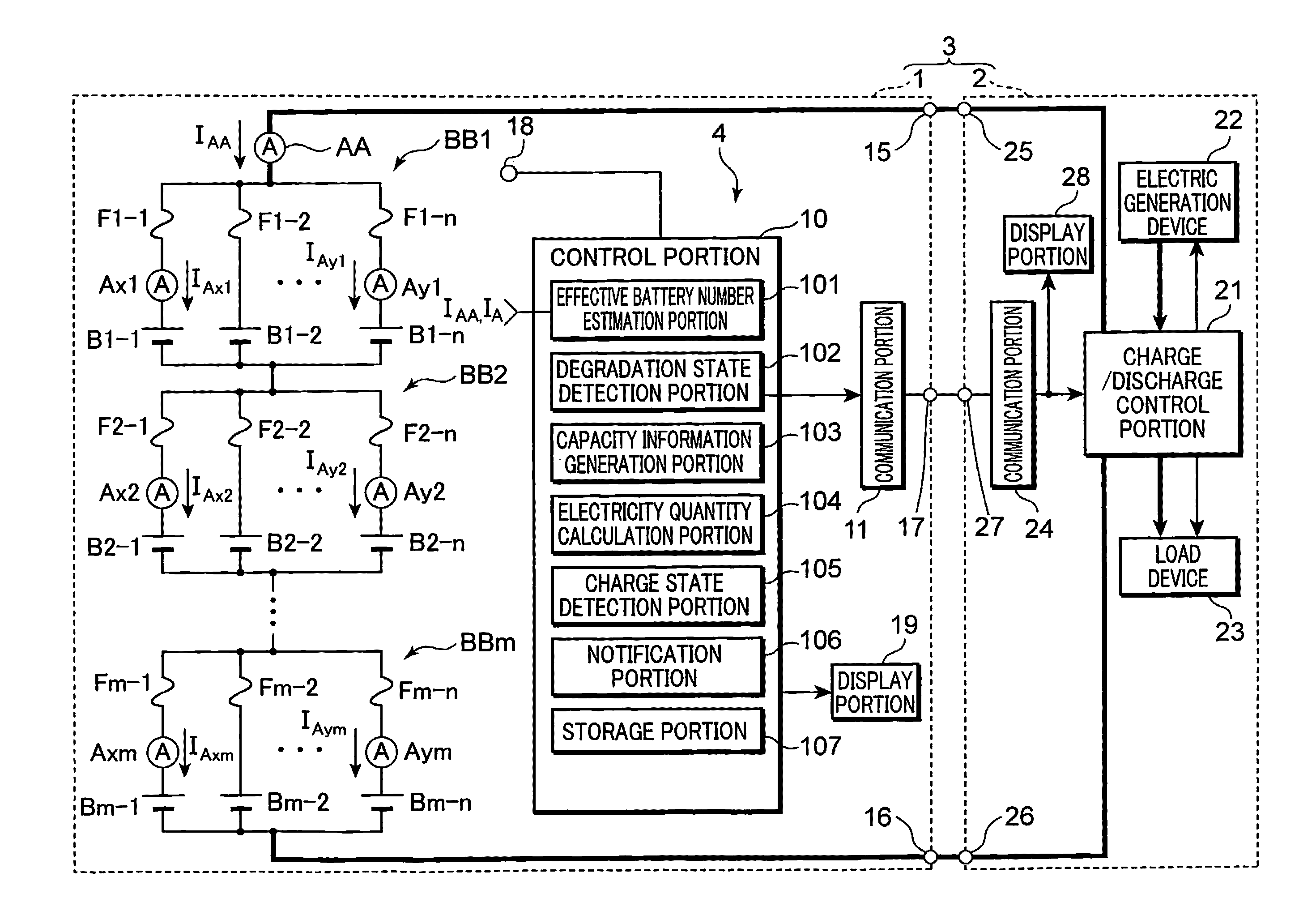
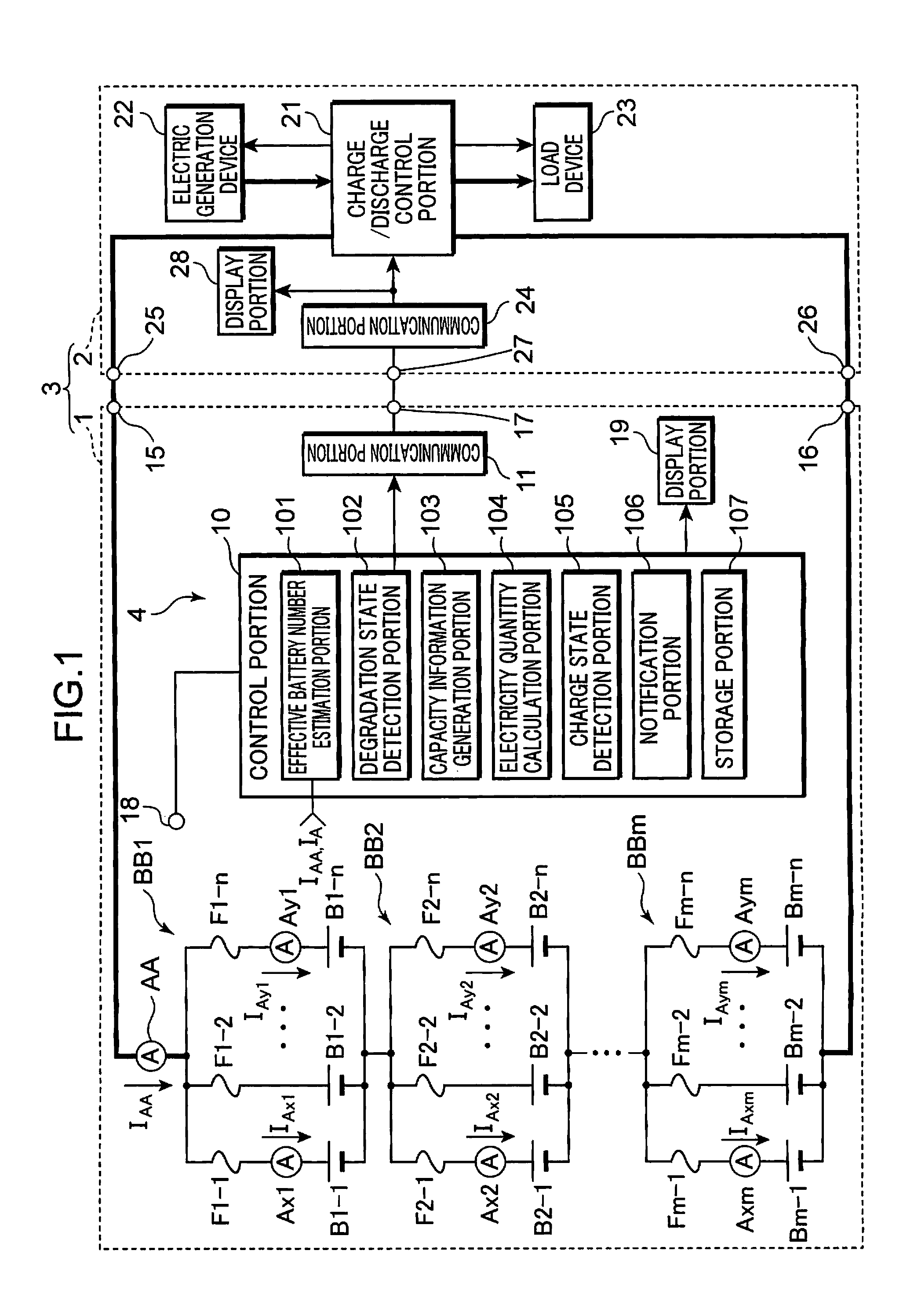
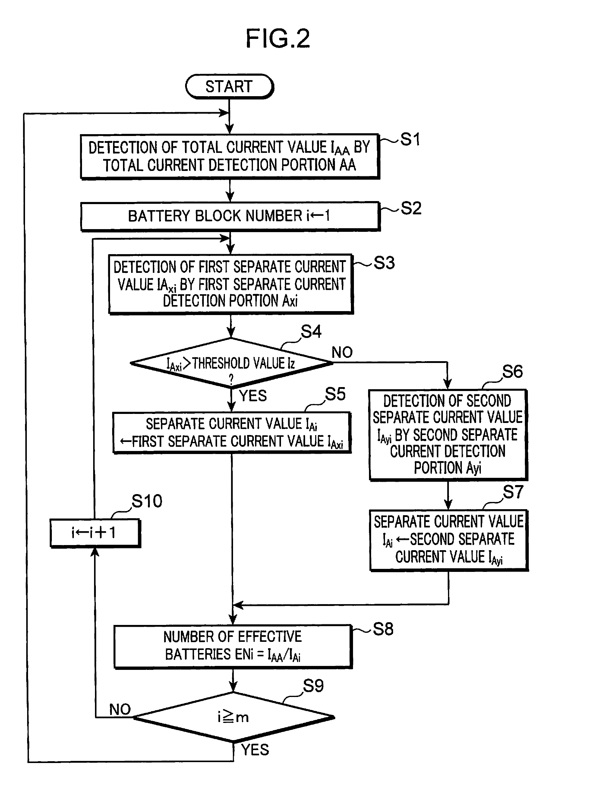
[0022]FIG. 1 is a block diagram showing one example of a battery power supply device using the charge state detection circuit of a first embodiment of the invention, and a battery power supply system comprising the battery power supply device.

[0023]The battery power supply system 3 shown in FIG. 1 is configured by combining a battery power supply device 1 and an external device 2. The battery power supply device 1 shown in FIG. 1 comprises m (for example, 10) battery blocks BB1 to BBm, a total current detection portion AA, a control portion 10, a communication portion 11, a temperature sensor 18, connection terminals 15, 16, 17, and a display portion 19.

[0024]And, the portions of the battery power supply device 1 excluding the battery blocks BB1 to BBm form a charge state detection circuit 4.

[0025]The m battery blocks BB1 to BBm are connected in series. And, the positive electrode of the series circuits of the battery blocks BB1 to BBm, that is, the positive electrode of the battery...

second embodiment

[0136]Next, a battery power supply device 1b comprising the charge state detection circuit 4b and a battery information monitoring device 5 of a second embodiment of the invention are explained. FIG. 6 is a block diagram showing one example of the configuration of the battery power supply device 1b and battery information monitoring device 5 of the second embodiment.

[0137]The battery power supply device 1b shown in FIG. 6 differs from the battery power supply device 1 shown in FIG. 1 in the following respects. That is, the battery power supply device 1b, similarly to the battery power supply device 1a shown in FIG. 5, comprises voltage detection portions VS1 to VSm and an internal resistance detection portion 108. The control portion 10b of the battery power supply device 1b also functions as an indicator value calculation portion 109 and ranking portion 110. Further, the notification portion 106b is also different in that, in addition to operations similar to those of the notificat...


PUM


Abstract

A charge state detection circuit, which detects a state of charge of a battery block in which are parallel-connected a plurality of series circuits of a secondary battery and a cutoff element which assumes a cutoff state of cutting off the charge/discharge path of the secondary battery and a conducting state different from the cutoff state, the charge state detection circuit comprising: an effective battery number detection portion which detects, as the number of effective batteries, the number of cutoff elements in the conducting state from among the plurality of cutoff elements included in the battery block; a capacity information generation portion which, based on the number of effective batteries, generates capacity information related to actual full charge capacity, which is the actual full charge capacity of the battery block; a total current detection portion, which detects as a total current value a current flowing in the entire battery block; an electricity quantity calculation portion, which calculates, as a stored electricity quantity, an electricity quantity stored in the battery block, by integrating the total current value; and a charge state detection portion, which, based on the capacity information and the stored electricity quantity, detects a state of charge, which is a ratio of the stored electricity quantity to the actual full charge capacity.

Description

TECHNICAL FIELD [0001]This invention relates to a charge state detection circuit which detects the charging state of a battery block, in which a plurality of secondary batteries are connected in parallel, a battery power supply device which uses this circuit, and a battery information monitoring device which monitors information relating to such a battery block.BACKGROUND ART [0002]In a battery power supply device of the prior art which supplies power to a load circuit using secondary batteries, in order to secure the output current required by the load circuit, a battery block in which a plurality of secondary batteries are connected in parallel is widely used.[0003]In such a battery power supply device, when an overcurrent, overheating, or another abnormality occurs in a portion of the secondary batteries in a battery block, if charging and discharging of the battery block are performed in the same manner as usual, there is the concern that the secondary batteries may be caused to...

Claims


Application Information

Patent Timeline
IPC IPC(8): G01R31/36
CPCH01M10/441H01M10/465Y02T10/7055H02J7/0016H02J7/0021H01M10/482Y02T10/70Y02E60/10H02J7/0013H02J7/0048H02J7/005H02J7/0014
Inventor IIDA, TAKUMA
Owner PANASONIC CORP
Why Eureka
Try Eureka