

Image synthesizing device, coding device, program, and recording medium
a synthesizing device and image technology, applied in the direction of signal generators with optical-mechanical scanning, selective content distribution, television systems, etc., can solve the problems of obstructing the view of subtitles and frequency obstructing the view of areas, and achieve the effect of easy synthesizing object graphics onto the proper area
- Summary
- Abstract
- Description
- Claims
- Application Information
AI Technical Summary
Benefits of technology
Problems solved by technology
Method used
Image

Examples
embodiment
[0070]First, an embodiment (FIGS. 1 to 7) is described. Then, modifications (FIGS. 8 to 18) of the embodiment are described.
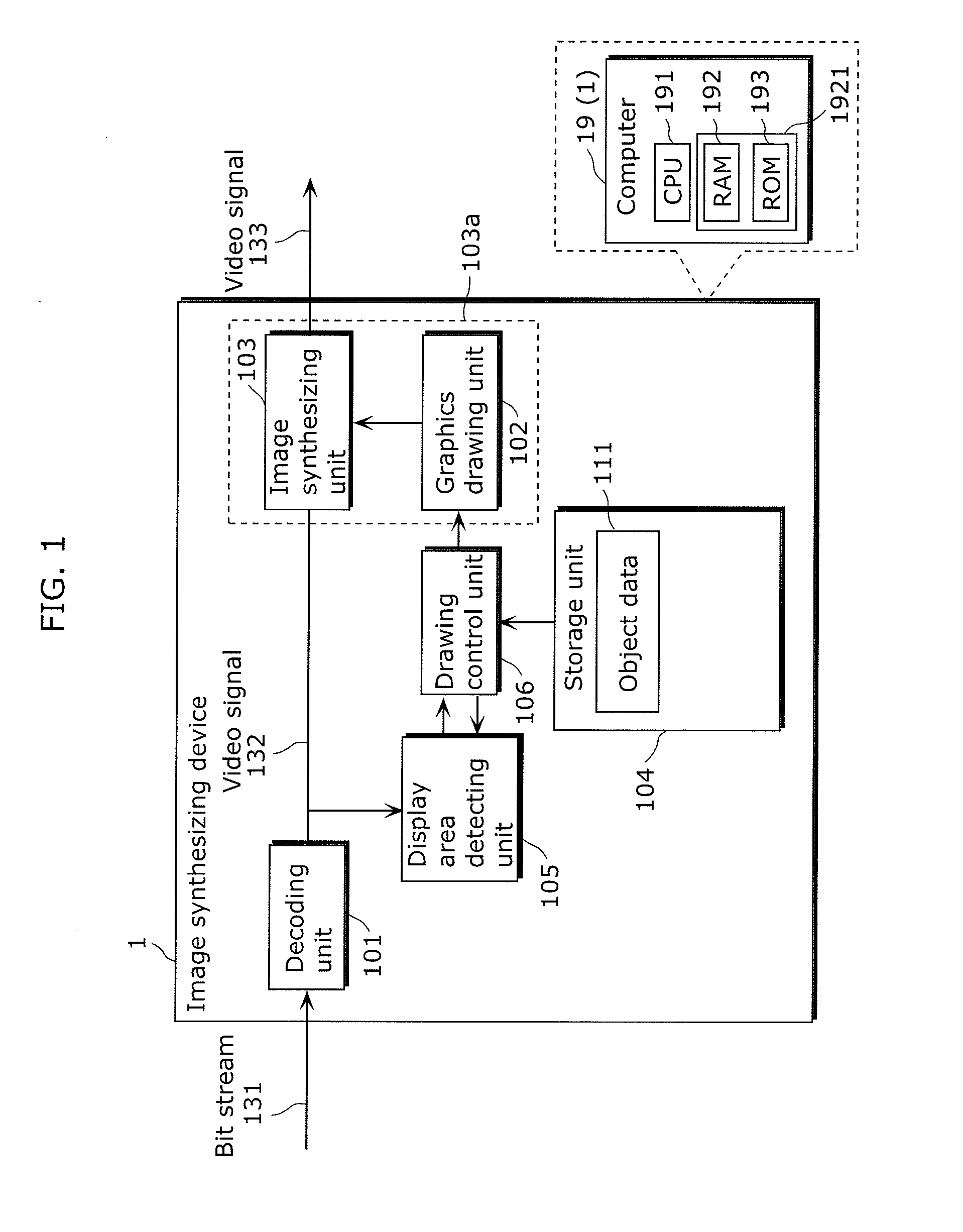
[0071]The following describes an image synthesizing device 1 (FIG. 1) which determines, in a decoded image, an area having a low spatial frequency, and synthesizes a graphics object (synthesis target image) onto the determined area. It is to be noted that here, for the sake of simplification, a case is described as an example where the image synthesizing device 1 synthesizes a subtitle as a graphics object onto an image obtained by decoding a bit stream which is recorded in HD resolution (1920 pixels×1080 lines) and compliant with the ISO / IEC 14496-10.
[0072]FIG. 1 is a block diagram showing the image synthesizing device 1 according to the embodiment.
[0073]In the image synthesizing device 1, a decoding unit 101 decodes a bit stream 131 inputted to the image synthesizing device 1 from a digital broadcast signal receiving unit or a storage unit. Then, an image syn...
modification 1
[0155]The following describes an image synthesizing device 2 according to Modification 1 of the embodiment. The image synthesizing device 2 defines, for each type of graphics object, at least one display target area which specifies a display area of an object. Moreover, the image synthesizing device 2 narrows down, for each display time of the graphics object, an area that can be displayed from among the display target areas. It is to be noted that here, for the sake of simplification, a case is described as an example where the image synthesizing device 2 performs synthesis on an image obtained by the decoding unit 101 decoding a bit stream which is recorded in HD resolution (1920 pixels×1080 lines) and compliant with the ISO / IEC 14496-10, as in the case described in the embodiment. The image synthesizing device 2 performs the synthesis on a subtitle as the graphics object.
[0156]FIG. 8 is a block diagram showing the image synthesizing device 2 according to Modification 1.
[0157]FIG....
modification 2
[0171]The following describes an image synthesizing device 3 according to Modification 2 of the embodiment which waits for stabilization of a display position of a graphics object at the time of a scene change. It is to be noted that here, for the sake of simplification, a case is described as an example where the image synthesizing device 3 performs synthesis on an image obtained by the decoding unit 101 decoding a bit stream which is recorded in HD resolution (1920 pixels×1080 lines) and compliant with the ISO / IEC 14496-10, as in the case described in the embodiment. The image synthesizing device 3 performs the synthesis on a subtitle as the graphics object.
[0172]FIG. 10 is a block diagram showing the image synthesizing device 3 according to Modification 2.
[0173]The image synthesizing device 3 decodes the bit stream 131 inputted from the digital broadcast signal receiving unit, the storage unit or the like, and synthesizes a graphics object onto the decoded video signal 132. The i...
PUM
 Abstract
Description
Claims
Application Information