
Solar-powered lighting module

Active Publication Date: 2012-05-17
UNIV OF FLORIDA RES FOUNDATION INC
View PDF14 Cites 31 Cited by
  • Summary
  • Abstract
  • Description
  • Claims
  • Application Information

AI Technical Summary

Benefits of technology

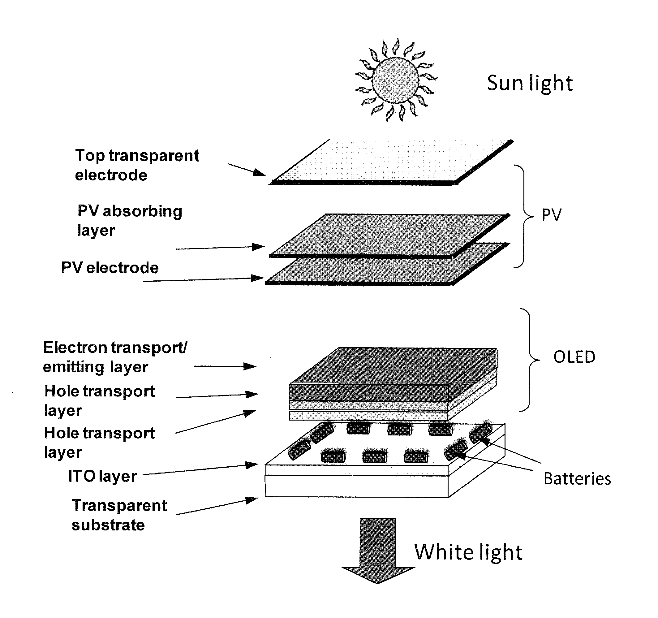
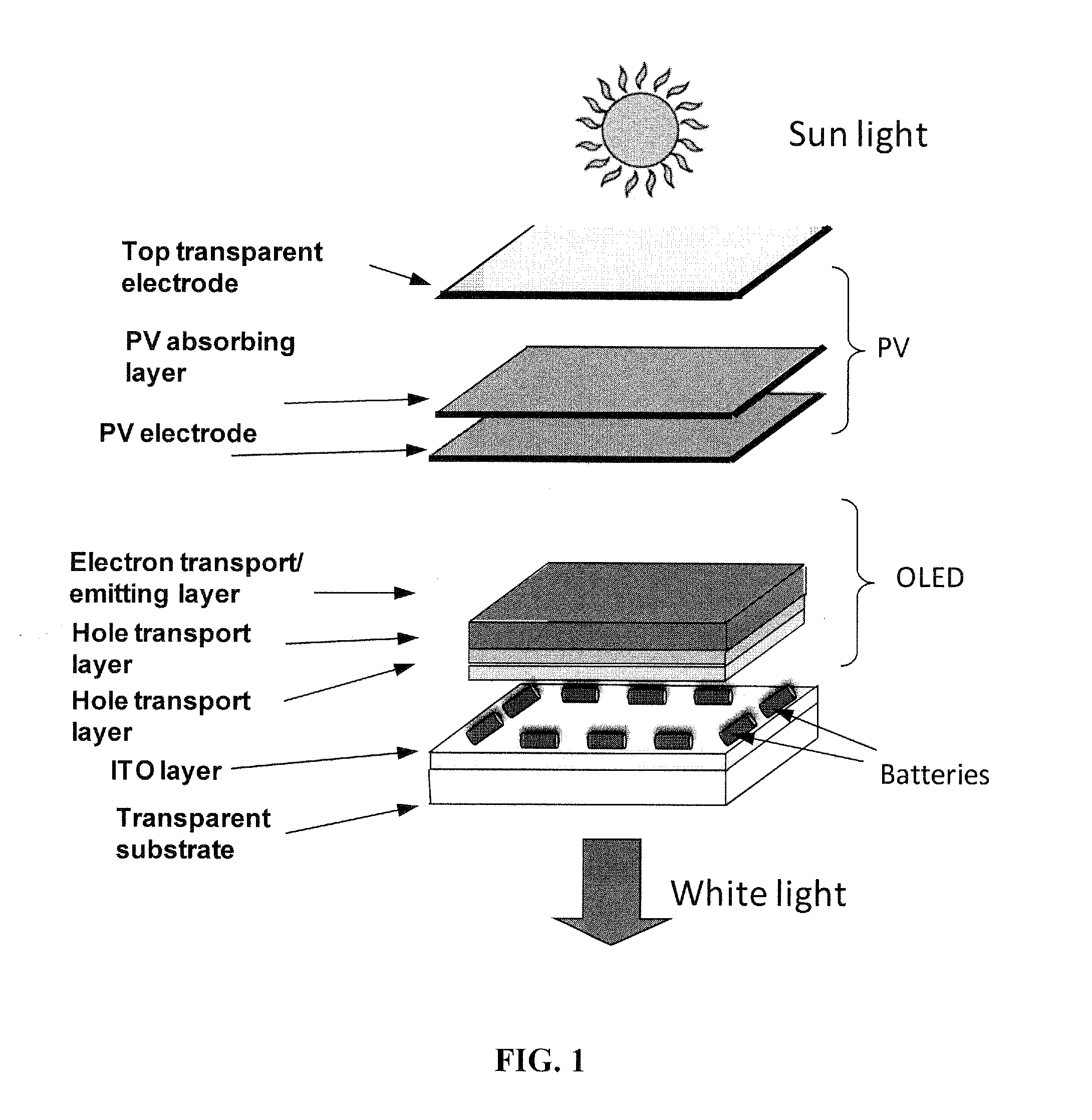
[0008]In an embodiment, a solar-powered lighting module is provided, including a solar cell, for generating electricity when exposed to light, and a light generating device capable of being powered by the generated electricity. In a further embodiment, the module further includes a battery for storing charge from the generated electricity. In an embodiment, the module further includes a controller that regulates the current transmitted between the components of the module. As the lighting provided by the module can be, at least partially, solar-powered, use of the module can reduce the amount of electricity needed for lighting commercial and residential buildings.
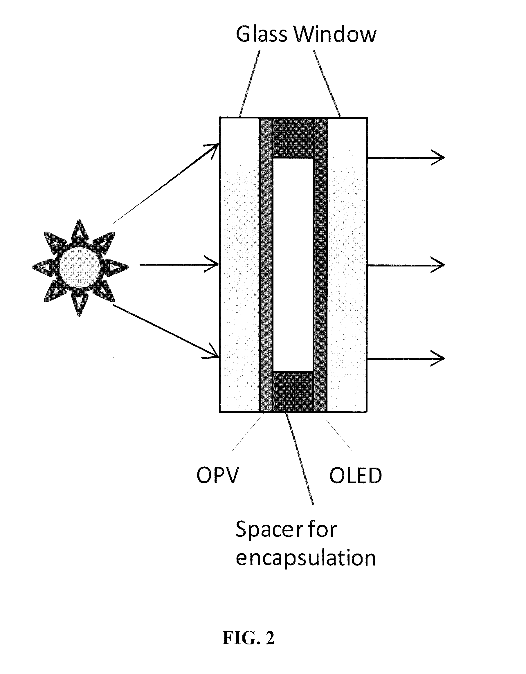
[0011]In further embodiments, a module, such as one or more of the modules discussed above or throughout the subject application, can serve as an interface between two environments. In a specific embodiment, a module can serve as an interface between the inside and outside of an environmentally controlled space. In an embodiment, the module is incorporated into a building interface, such as a window, skylight, or other interface and can be positioned to light an interior portion of the building. In another embodiment, the solar cell and light generating device can be, partially or wholly, transparent to allow light to pass through the interface. In a further embodiment, tinted-color conjugated polymers incorporated into the module limit the spectrum of light that can pass through the interface. In an embodiment, the interface provides good thermal insulation and low sun-light transmission that further reduce the electricity required for heating and air conditioning the controlled space.

Problems solved by technology

Inefficient lighting not only impacts the electricity directly consumed due to lighting, it also affects overall electricity consumption because inefficient lighting sources contribute to a building's internal heat generation and subsequent air-conditioning loads.
These incandescent light bulbs are extremely inefficient with more than 90% of the energy consumed contributing to heat generation.
But these devices are often still attached to the power-grid.

Method used


Image

  • Solar-powered lighting module
  • Solar-powered lighting module
  • Solar-powered lighting module

Examples


Embodiment Construction

[0033]Embodiments of the invention are directed to high-efficiency, solar-powered lighting. In an embodiment, a light generating device is provided. In another embodiment, a power generation device is provided. In a particular embodiment, the power generation device incorporates a solar cell. In yet another embodiment, an energy storage device is provided. In a particular embodiment, the energy storage device includes a battery.

[0034]In an embodiment, a solar-powered lighting module is provided, including a solar cell for generating electricity when exposed to light and a light generating device capable of being powered by the generated electricity. In a further embodiment, the module further includes a battery for storing charge from the generated electricity. In an embodiment, the module further includes a controller that regulates the current transmitted between the components of the module.

[0035]In an embodiment, an electricity generation module is provided, including a solar ce...


PUM

PropertyMeasurementUnit
Currentaaaaaaaaaa
Transparencyaaaaaaaaaa
Wavelengthaaaaaaaaaa

Abstract

A solar-powered lighting module is provided, including a solar cell for generating electricity when exposed to light, a battery for storing charge from the generated electricity, and a light generating device powered by the stored charge. In an embodiment, the module further includes a controller that regulates the current transmitted between the components of the module. In a further embodiment, the module is incorporated into an interface to an environmentally controlled space and can be positioned to light an interior portion of the space. In another embodiment, the solar cell and light generating device are transparent to allow light to pass through the interface. In a further embodiment, tinted-color conjugated polymers incorporated into the module limit the spectrum of light that can pass through the interface. In yet another embodiment, a method of modifying an existing interface with such a module is provided.

Description

CROSS-REFERENCE TO RELATED APPLICATION[0001]The present application claims the benefit of U.S. Provisional Application Ser. No. 61 / 183,359, filed Jun. 2, 2009, which is hereby incorporated by reference herein in its entirety, including any figures, tables, or drawings.GOVERNMENT SUPPORT[0002]The subject invention was made with government support under a research project supported by Florida Energy Systems Consortium, Contract No. 00080583. The government has certain rights to this invention.BACKGROUND OF INVENTION[0003]Lighting is the second largest end-use of energy in buildings. Energy consumption for all lighting in the U.S. is estimated to be 8.2 quads, or about 22% of the total electricity generated in the U.S. According to the Department of Energy Solid State Lighting Program Multi-Year Program Plan, more than half of these 8.2 quads are consumed in the commercial sector, the largest energy user for lighting. Nationally, in the residential and commercial sectors, lighting cons...

Claims


Application Information

Patent Timeline
IPC IPC(8): F21S9/03
CPCB82Y10/00E06B9/24E06B2009/2464E06B2009/247E06B2009/2476F21S9/037H01L2251/5361H01L27/288H01L27/3232H01L51/0036H01L51/0047H01L51/4253H01L2251/5323H01L27/281H10K19/201H10K65/00H10K59/50H10K85/215H10K85/113H10K30/30H10K2102/3031H10K39/10
Inventor MENG, YING S.SO, FRANKYXUE, JIANGENGZAWOY, KARL R.REYNOLDS, JOHN R.
Owner UNIV OF FLORIDA RES FOUNDATION INC
Learn More