
Thermal displacement compensation method and thermal displacement compensation device for machine tool

a compensation device and machine tool technology, applied in the direction of electric programme control, program control, instruments, etc., can solve the problems of affecting the quality of the machine tool

Active Publication Date: 2012-05-17
FANUC LTD
View PDF32 Cites 19 Cited by
  • Summary
  • Abstract
  • Description
  • Claims
  • Application Information

AI Technical Summary

Benefits of technology

The present invention provides a thermal displacement compensation method and device for a machine tool that can compensate for thermal displacement even when the machine is in use. The method involves calculating the thermal displacement of the machine's feed axis and detecting the position of the machine's movable part using a position sensor. The position sensor's output is used to determine the initial position of the feed axis. The thermal displacement compensation amount is then determined based on the difference between the initial position and the position of the feed axis during operation. The compensation amount can be increased or reduced based on the position of the machine and the ambient temperature. The thermal displacement compensation device includes a feed shaft thermal displacement amount calculation means, a thermal displacement compensation amount calculation means, and a compensation error calculation means. The position detection means can be set in a position that allows detection of the movable part's position during machining. The invention allows for accurate compensation for thermal displacement even during machining, improving the machine's performance and stability.

Problems solved by technology

In a machine tool, a feed screw and spindle are driven by a motor, so that they are expanded by heat from the motor, frictional heat from rotating bearings, frictional heat from an engaging portion between a ball screw and nut of the feed screw, thereby causing a shift in machine position.
This shift in machine position due to heat impedes high-precision machining.
Since the computational formula includes other coefficients (heat loss coefficient and heat conduction coefficient for calculation of heat conduction from adjacent sections), the accuracy of compensation cannot be further improved by only modifying the heat generation coefficient, in some cases.
Therefore, accurate compensation based on the ball screw position cannot be achieved by this method.
Since the distribution of thermal displacements in the individual positions of the ball screw is out of consideration in this case, however, accurate compensation cannot be achieved.(4) A technique disclosed in Japanese Patent Application Laid-Open No. 2002-144192 is an inter-two-point displacement compensation method for a feed screw, in which a difference between two points at the opposite ends of the feed screw is obtained, and error compensation is performed for the entire stroke for which an origin shift amount and pitch error compensation amount are determined by the difference.
Since the distribution of thermal displacements in the individual positions of the ball screw is out of consideration in this case, however, accurate compensation cannot be achieved.(5) In a technique disclosed in Japanese Patent Application Laid-Open No. 10-138091, a compensation amount is obtained according to an approximation formula based on an average moving speed, frequency of movement, moved position, and disturbance load torque of a feed shaft.
Since coefficients of a computational formula for estimating the thermal displacement amount and the like are not designed to be modified based on the result of the sensor measurement, the measurement result is not reflected in the estimation of subsequent thermal displacement amounts, so that the accuracy of the displacement amount estimation cannot be improved.

Method used

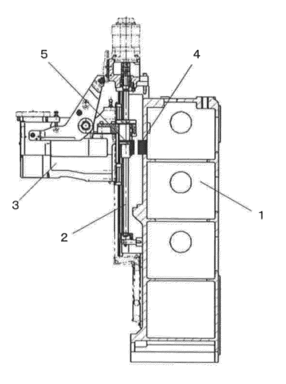
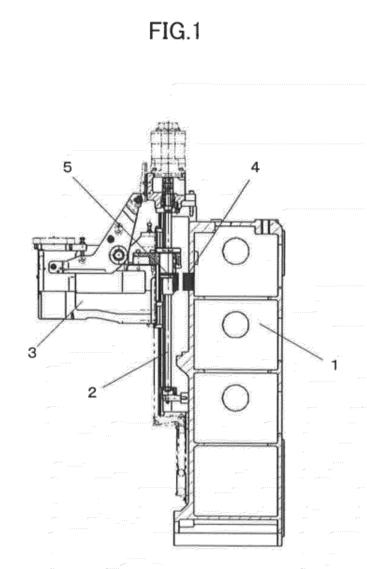
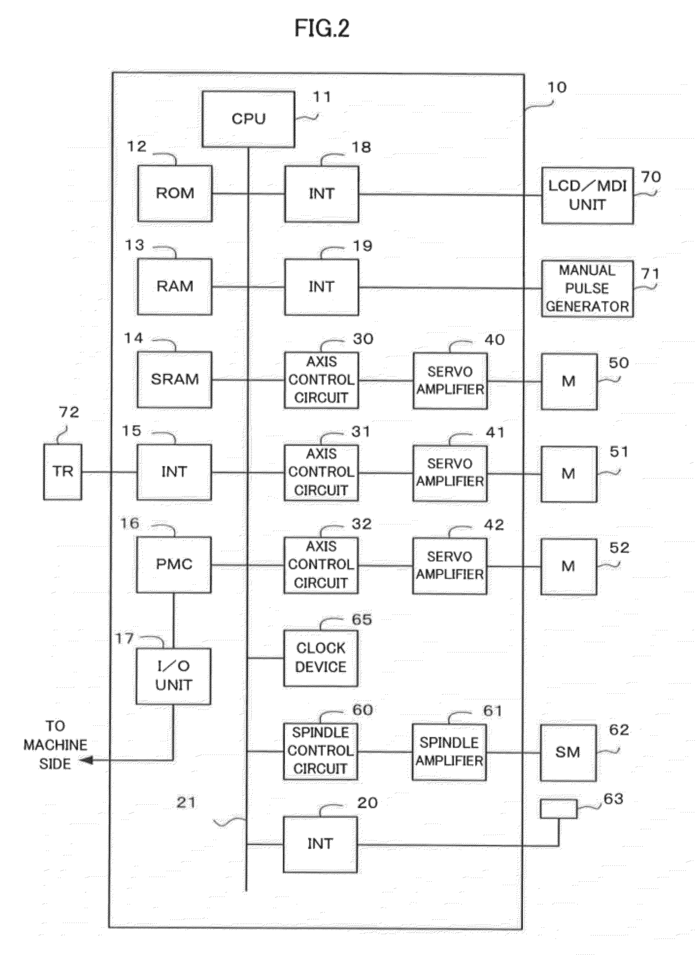

Image

  • Thermal displacement compensation method and thermal displacement compensation device for machine tool
  • Thermal displacement compensation method and thermal displacement compensation device for machine tool
  • Thermal displacement compensation method and thermal displacement compensation device for machine tool

Examples


first embodiment

[0058]B. The following is a description of a first embodiment for the thermal displacement compensation of the machine tool according to the present invention.

[0059](b1) Setting of sections for estimation and compensation of thermal displacement amount of feed axis:

[0060]The calculation and compensation of the thermal displacement amount of the feed axis will be described first. A calculation (estimation) method described here is the same as that disclosed in Japanese Patent Application Laid-Open No. 2002-18677 described before.

[0061]First, the overall length (stroke) of a feed screw 2 that constitutes a feed axis is divided into a plurality of sections, as shown in FIG. 3. The overall length of the feed screw 2 is equal to a distance from one end surface of a fixed bearing (specifically, an end surface of the fixed bearing on the side of a nut 6; defined as a reference position 7) that supports one end of the feed screw to one end surface of the nut 6 which is in engagement with th...

second embodiment

[0091]C. The following is a description of a second embodiment for thermal displacement compensation of a machine tool according to the present invention.

[0092](c1) Setting of sections for estimation and compensation of thermal displacement amount of feed axis:

[0093]Since this processing is performed in the same manner as “(b1) Setting of sections for estimation and compensation of thermal displacement amount of feed axis” according to the first embodiment, a description thereof is omitted.

[0094](c2) Compensation of thermal displacement of feed axis:

[0095]Since this processing is performed in the same manner as “(b2) Compensation of thermal displacement of feed axis” according to the first embodiment, a description thereof is omitted.

[0096](c3) Calculation of thermal displacement amount of feed axis:

[0097]In calculating the thermal displacement amount of the feed axis, the processing shown in the flowchart of FIG. 7 is performed for each predetermined period (e.g., for each second)....

third embodiment

[0113]D. The following is a description of a third embodiment for thermal displacement compensation of a machine tool according to the present invention.

[0114]In the first and second embodiments described above, the feed shaft thermal displacement amount is calculated by dividing the overall length of the feed axis into a plurality of sections and obtaining the thermal displacement amount for each section.

[0115]The present invention is not limited to the methods described in connection with the first and second embodiments, and is also applicable to a method in which a feed shaft thermal displacement amount is obtained without dividing a feed axis into sections, as in a third embodiment. In this third embodiment, as in the first and second embodiments, a compensation error in a previously stored initial position is obtained from the difference between the initial position and an actual position.

[0116]In obtaining an error compensation rate, as described in connection with “(b4) Calc...


PUM


Abstract

In a thermal displacement compensation method for a machine tool, in which a feed shaft thermal displacement amount is obtained and an amount which cancels the obtained feed shaft thermal displacement amount is added as a thermal displacement compensation amount to a position command for a feed axis, a position where a signal is first output by a position sensor for detecting the position of a movable part of the machine tool is first stored as an initial position. Then, the position where the signal is output by the position sensor is detected, and the thermal displacement compensation amount is modified according to a compensation error, which is the difference between the detected position (actual position) and the initial position.

Description

BACKGROUND OF THE INVENTION[0001]1. Field of the Invention[0002]The present invention relates to a thermal displacement compensation method and a thermal displacement compensation device for a machine tool.[0003]2. Description of the Related Art[0004]In a machine tool, a feed screw and spindle are driven by a motor, so that they are expanded by heat from the motor, frictional heat from rotating bearings, frictional heat from an engaging portion between a ball screw and nut of the feed screw, thereby causing a shift in machine position. Thus, the relative positions of a workpiece to be positioned and a tool are shifted. This shift in machine position due to heat impedes high-precision machining.[0005]Conventionally, some techniques and structures have been used to prevent this heat-induced shift of the machine position. In one such technique, thermal displacement is simply compensated at low cost without using a temperature sensor. In another technique, a command position is compensa...

Claims


Application Information

Patent Timeline
Patent Type & Authority Applications(United States)
IPC IPC(8): G05B19/19
CPCG05B2219/49207G05B19/404G05B2219/49212
Inventor MAEKAWA, SUSUMUENDOU, TAKAHIRO
Owner FANUC LTD
Learn More