Method and apparatus for joint motion simulation

a joint motion and simulation technology, applied in the field of joint motion simulation, can solve the problems of polyethylene wear, infection, mal-alignment, polyethylene wear can predispose implants to loosening, new and more complex modes of wear, damage, failure, etc., and achieve the effect of improving motion control

Active Publication Date: 2012-05-17
ADVANCED MECHANICAL TECH
View PDF8 Cites 15 Cited by
  • Summary
  • Abstract
  • Description
  • Claims
  • Application Information

AI Technical Summary

Benefits of technology

[0005]The present invention is generally directed to apparatus and methods for joint motion simulation that provide enhanced motion control to a prosthetic simulator. The prosthetic simulator provides a non-human environment in which to evaluate new and existing prosthetic devices, particularly implantable prosthetic devices, through accelerated life testing.

Problems solved by technology

Among the most prevalent causes of failure are polyethylene wear, loosening, infection, and mal-alignment.
Moreover, polyethylene wear can predispose implants to loosening as a result of increased loading of the reformed tissues.
As implant technology evolves, new and more complex modes of wear, damage, and failure are being identified.

Method used


Image

  • Method and apparatus for joint motion simulation
  • Method and apparatus for joint motion simulation
  • Method and apparatus for joint motion simulation

Examples


Embodiment Construction

[0030]A description of example embodiments of the invention follows.

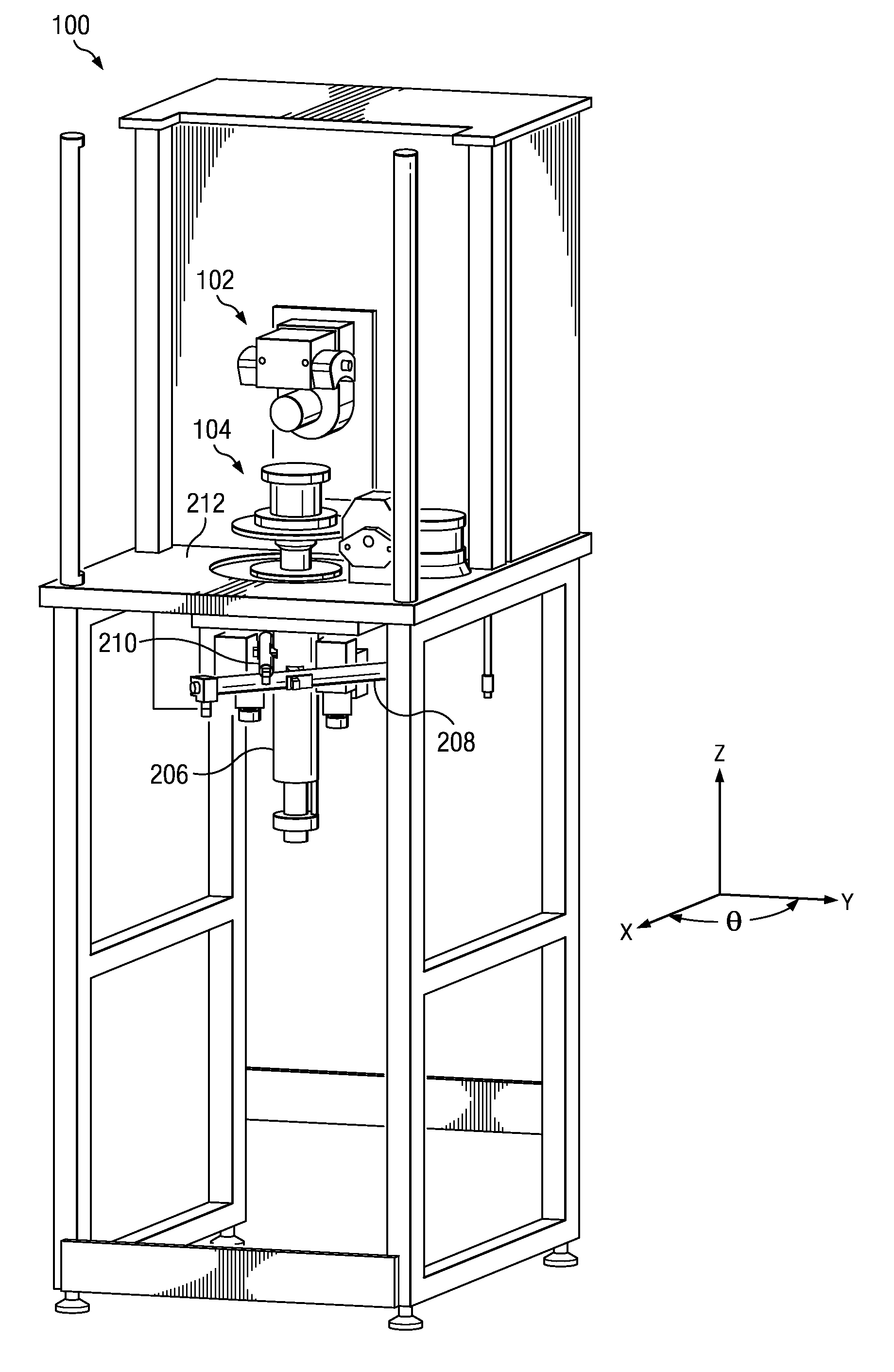
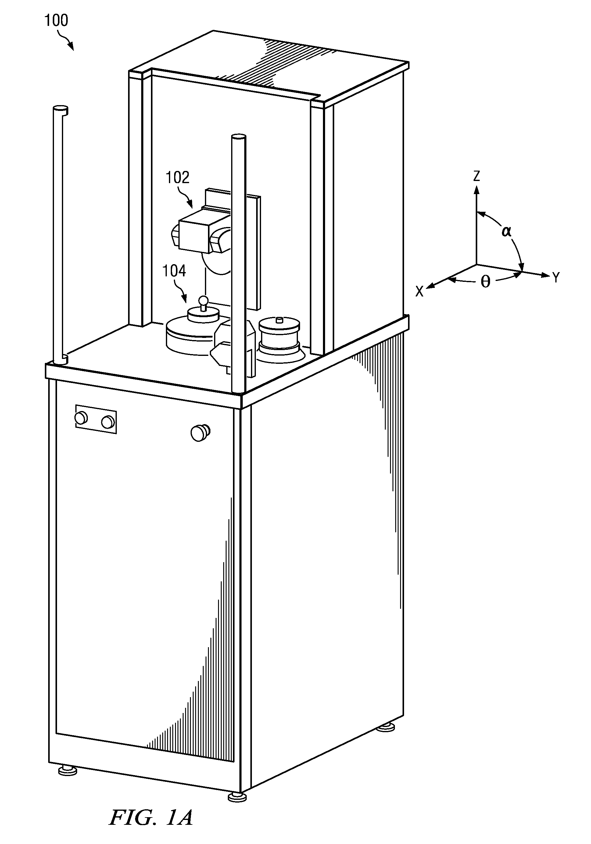
[0031]FIG. 1A illustrates a simulation system 100 embodying the present invention. As with prior systems, one element of the joint is mounted into an upper mount 102 and the other element of the joint is mounted to a lower mount (platform) 104. The lower mount 104, also referred to herein as the specimen stage or mechanical stage, is controllable with X-Y-Z-θ degrees of freedom.

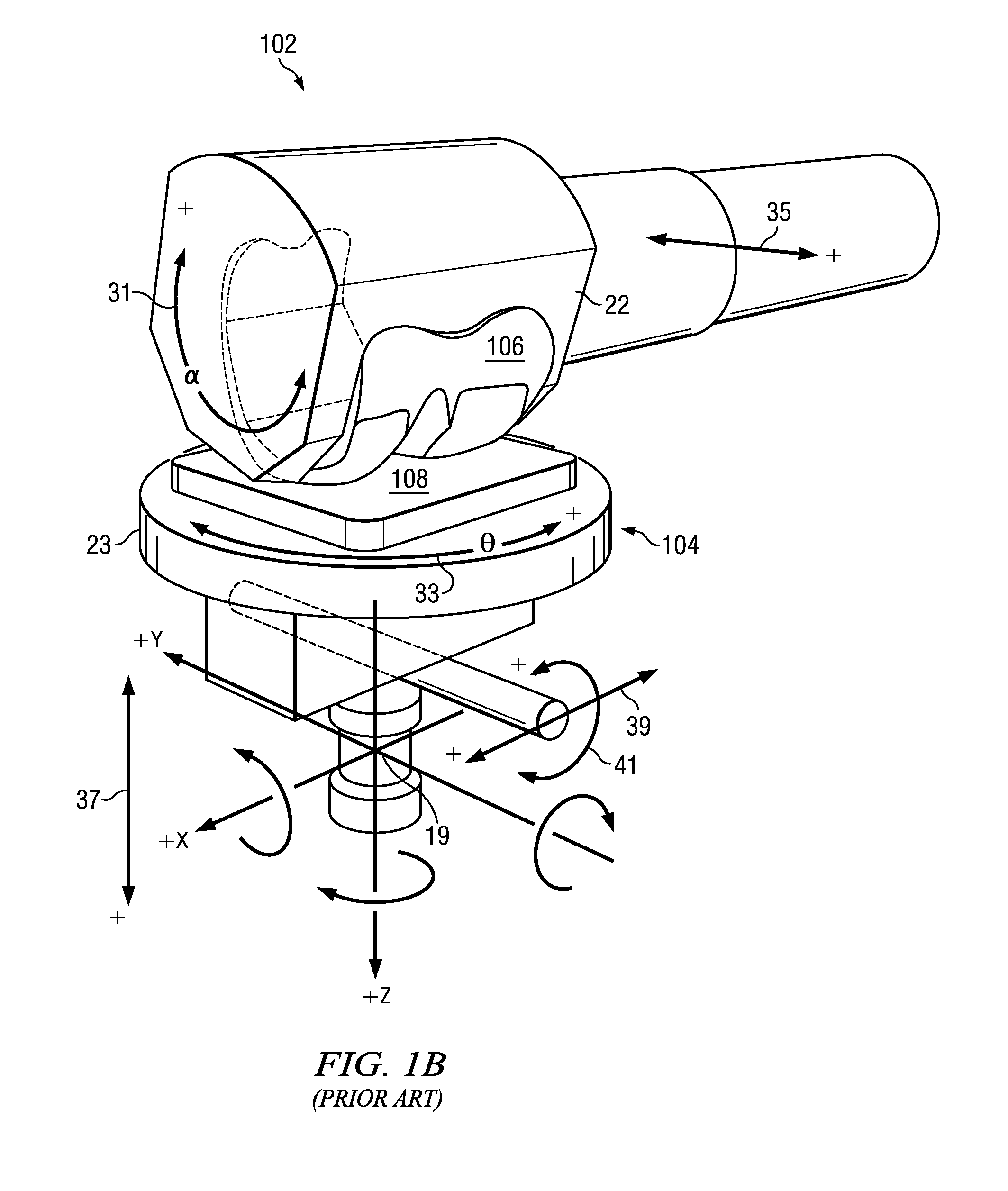
[0032]FIG. 1B illustrates a prosthetic knee joint, though the system can carry prosthetic elements of any joint. The joint elements 106, 108 butt against each other between the two mounts and are separately driven through a programmed motion. A prior simulation system is described in the U.S. Pat. No. 7,823,460 to Bruce F. White, which is incorporated by reference in its entirety. In the prior simulation system, the upper mount was moveable by actuators in the lateral Y direction 35 and was also rotatable 31 about a front to rear axis X with ...


PUM


Abstract

A joint motion simulator to simulate biomechanical motion includes a mount to which a prosthetic device is mounted, actuators coupled to the mount to drive the mount, and a programmable controller to drive the actuators to translate the mount and to rotate the mount with a center of rotation controllable independent of translation. The simulator can include a linear actuator to translate the mount in a linear direction substantially parallel to the axis of rotation. The linear actuator can include a piston within a sleeve, the piston being coupled to the mount and being hydraulically driven to translate the mount, and the actuators can be coupled to the sleeve. The controller may be programmed to vary the center of rotation with linear translation and rotation of the mount. Sensors may be included that measure displacement of the actuators. The controller may drive the actuators based on the measured displacement.

Description

RELATED APPLICATION[0001]This application claims the benefit of U.S. Provisional Application No. 61 / 413,873, filed on Nov. 15, 2010.[0002]The entire teachings of the above application are incorporated herein by reference.BACKGROUND OF THE INVENTION[0003]Prosthetic implant failure mechanisms are numerous. Among the most prevalent causes of failure are polyethylene wear, loosening, infection, and mal-alignment. Polyethylene wear comprises the largest single identifiable cause of implant failure today. Moreover, polyethylene wear can predispose implants to loosening as a result of increased loading of the reformed tissues. As implant technology evolves, new and more complex modes of wear, damage, and failure are being identified. As a consequence of these facts, there is a great need for rigorous implant life cycle testing in simulator machines that are capable of replicating the subtleties of human motion.[0004]Simulator machines address the implant longevity problem by providing a no...

Claims


Application Information

Patent Timeline
Patent Type & Authority Applications(United States)
IPC IPC(8): G05B15/02
CPCA61F2/38G09B23/32A61F2/468A61F2/70A61F2/76Y10T74/20207Y10T74/20348A61F2002/701A61F2002/704A61F2/741B25J17/0266
Inventor CARIGNAN, FOREST J.WHITE, BRUCE F.
Owner ADVANCED MECHANICAL TECH
Why Eureka
Try Eureka