
Switch circuit and method for switching input/output port and electronic device using the same

Inactive Publication Date: 2012-05-17
ASUSTEK COMPUTER INC
View PDF3 Cites 2 Cited by
  • Summary
  • Abstract
  • Description
  • Claims
  • Application Information

AI Technical Summary

Benefits of technology

[0008]A conventional eSATA function is usually provided in three modes. In a first mode, the eSATA cooperates with an independent control chip, and however, the manufacture cost is increased. In a second mode, a built-in SATA interface of a south bridge chip is connected to a back panel of the computer casing to be used as an eSATA port. In a third mode, the built-in SATA port is converted to the eSATA port via a SATA-to-eSATA cable. However, the available built-in SATA port is occupied in the second and third modes, and thus less built-in devices can be installed. Moreover, since the number of the channel of the PCIe interface supported by the south bridge chip is limited, if the number of the built-in SATA port and the eSATA port is increased, the limited channel number of the PCIe interface is occupied.

Problems solved by technology

To expand storage capacity externally, the user needs to open the computer casing, and install or replace a hard disk with larger capacity, which is quite inconvenience for users.
In a first mode, the eSATA cooperates with an independent control chip, and however, the manufacture cost is increased.
However, the available built-in SATA port is occupied in the second and third modes, and thus less built-in devices can be installed.
Moreover, since the number of the channel of the PCIe interface supported by the south bridge chip is limited, if the number of the built-in SATA port and the eSATA port is increased, the limited channel number of the PCIe interface is occupied.

Method used


Image

  • Switch circuit and method for switching input/output port and electronic device using the same
  • Switch circuit and method for switching input/output port and electronic device using the same
  • Switch circuit and method for switching input/output port and electronic device using the same

Examples


Embodiment Construction

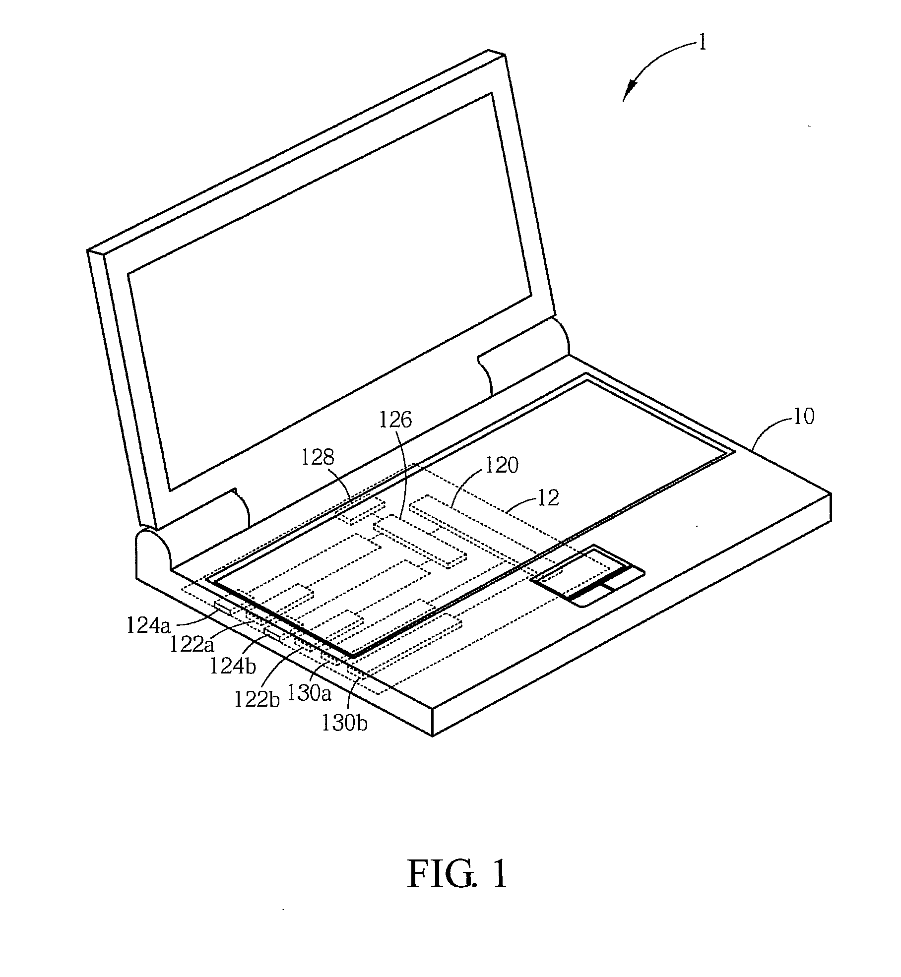
[0017]FIG. 1 is a schematic diagram showing an electronic device in an embodiment. Hereinafter, a notebook is taken as an example of an electronic device 1, which is not limited herein. The electronic device 1 includes a casing 10 and a motherboard 12. The motherboard 12 is disposed in the casing 10. In general, except motherboard 12, the casing 10 also includes other electronic components (not shown) with different functions, such as a fan, a hard disk, an optical disk drive (ODD) and a power supply. The function of the electronic components can be achieved by persons having ordinary skill in the art, which is omitted herein.

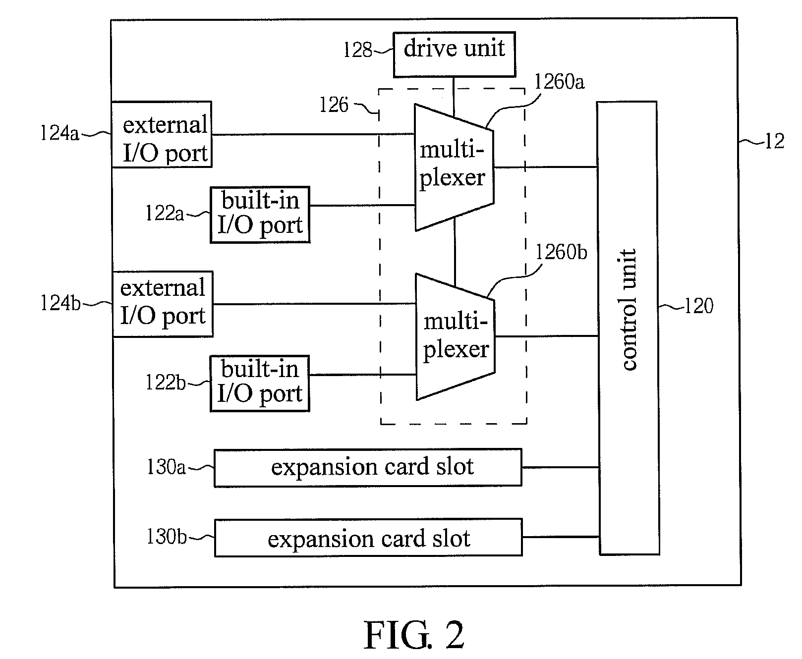
[0018]As shown in FIG. 1, the motherboard 12 includes a control unit 120, built-in I / O ports 122a and 122b, external I / O ports 124a and 124b, a switch unit 126, a driver 128 and expansion card slots 130a and 130b, where the control unit 120, the built-in I / O ports 122a and 122b, the external I / O ports 124a and 124b, the switch unit 126 and the driver 128 form t...


PUM


Abstract

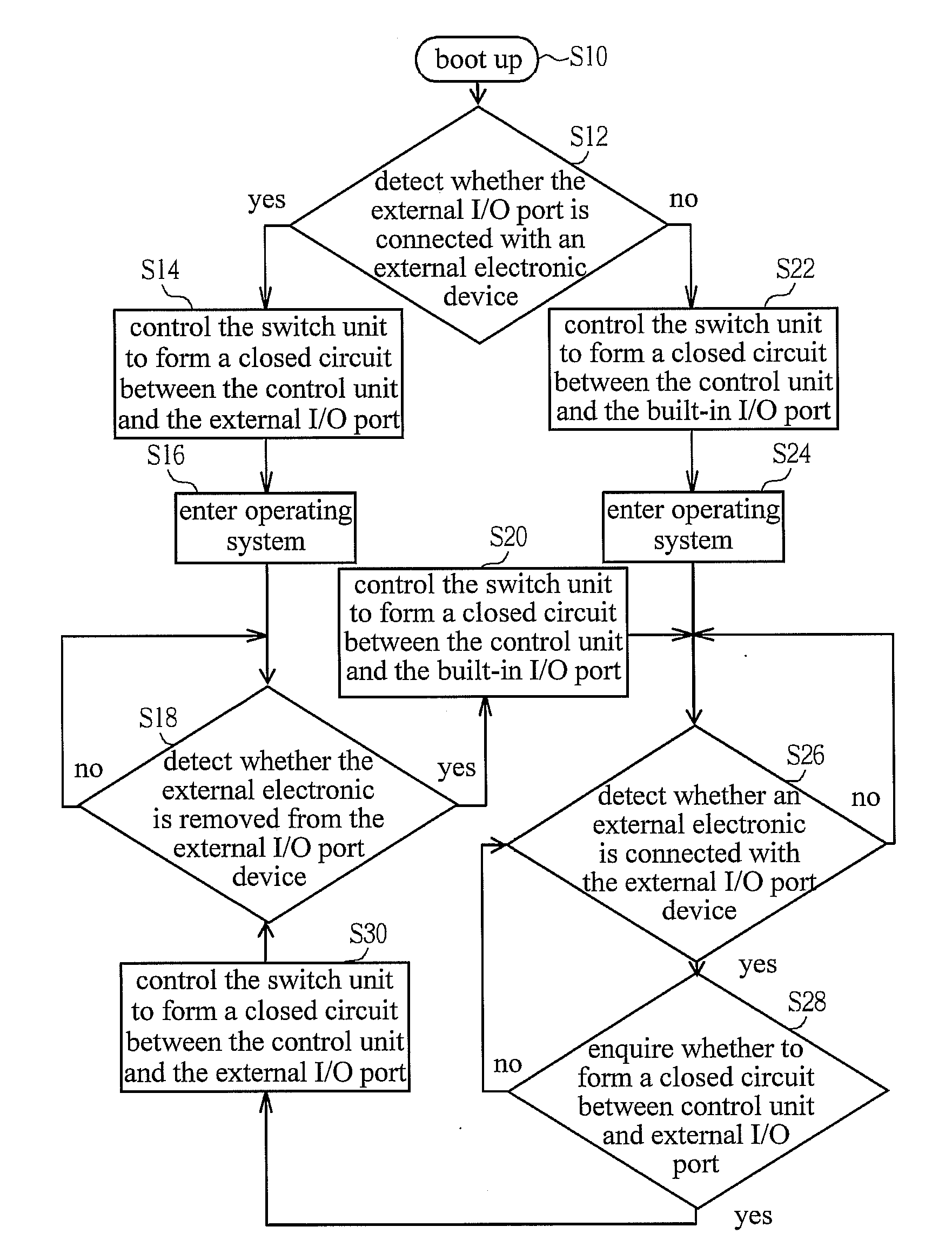
A switch circuit for switching input / output port includes a control unit, a built-in input / output (I / O) port, an external I / O port and a switch unit. The switch unit is electrically connected to the control unit, the built-in I / O port and the external I / O port. The switch unit receives a control signal and selectively forms a channel between the control unit and the built-in I / O port or between the control unit and the external I / O port accordingly.

Description

CROSS REFERENCE TO RELATED APPLICATIONS[0001]This Non-provisional application claims priority under 35 U.S.C. §119(a) on Patent Application No(s). 201010541751.6 filed in People's Republic of China on Nov. 12, 2010, the entire contents of which are hereby incorporated by reference.BACKGROUND OF THE INVENTION[0002]1. Field of Invention[0003]The invention relates to a switch circuit for switching an input / output port and a method thereof and, more particularly, to a switch circuit capable of switching between a built-in input / output (I / O) port and an external I / O port and a method thereof.[0004]2. Related Art[0005]A motherboard is used as a platform to connect components in a computer together. In general, a central processing unit (CPU) is like a brain which responsible for calculation, and the motherboard is like a spine that connects expansion cards, a hard disk, network, an audio device, a keyboard, a mouse, a printer and other peripheral devices to the CPU to control.[0006]In con...

Claims


Application Information

Patent Timeline
IPC IPC(8): G06F3/00
CPCG06F13/385
Inventor CHENG, HSU-HUNG
Owner ASUSTEK COMPUTER INC
Learn More