Floatable subsea platform (FSP)

Active Publication Date: 2015-08-13
CONOCOPHILLIPS CO
View PDF6 Cites 2 Cited by
  • Summary
  • Abstract
  • Description
  • Claims
  • Application Information

AI Technical Summary

Benefits of technology

[0022]The present invention involves a modular subsea facility and a method for installing it in deep waters with minimal use of ships specially equipped wi

Problems solved by technology

However, true offshore drilling and production did not take off until the first well was drilled completely out of site of land in 1947.
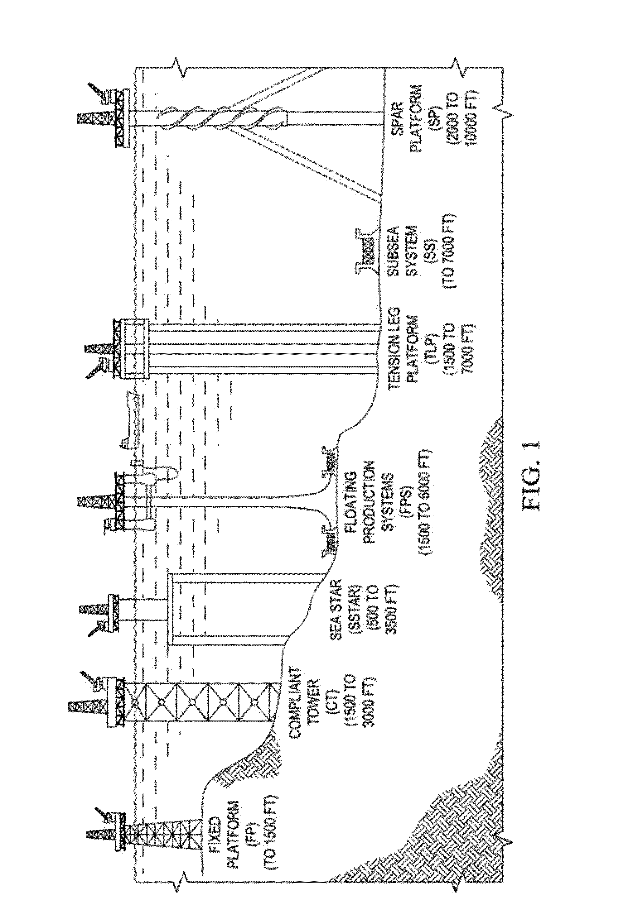
As drilling extends further offshore, rigs have become larger and more complex to meet the hostile environment.
Furthermore, time to perform operations are much greater in deep-water than shallow water operations.
Thus, deep-water drilling has been economically infeasible in the past.
However, for huge water depths, these methods are not very cost effective.
Furthermore, the requirement for the system to work deep underwater potentially reduces oil spills because connections must be sealed to prevent water ingress.
Equipment working at atmospheric pressure may not meet such design requirements.
Improvements in technology have allowed subsea facilities to perform numerous processes that have traditionally occurred at the surface, thus debottlenecking the processing capacity.
However, a disadvantage of subsea production systems is the cost of installation and maintenance of subsea equipment.
Accurate positioning requires time and skill and installation can be affected by bad weather on the surface.
The installation and maintenance of subsea equipment requires specialized and expensive methods, including regular diving equipment for shallow work up to 300 meters; one atmosphere diving equipment for work up to 700 meters; robotic equipment, generally remotely operated underwat

Method used


Image

  • Floatable subsea platform (FSP)
  • Floatable subsea platform (FSP)
  • Floatable subsea platform (FSP)

Examples


Embodiment Construction

[0060]The invention provides a novel subsea facility wherein the entire facility is attached to one or more modules equipped with buoyancy tanks. The modules can be latched together quayside to form a floatable subsea platform (FSP), or can be connected to one or more subplatform bases, or combinations thereof based on size, weight and towing considerations.

[0061]With this design, the subsea equipment can be connected and tested in the air or shallow water before being towed to the deep water well location, wherein the entire platform or subparts thereof, can be lowered, via controlled buoyancy, to the sea floor where the FSP is attached to a pre-installed template or other anchorage devices. It is believed that by setting the system up quayside, any repairs and installation issues can be performed quickly and without the specialized equipment and personnel normally needed for deep water installations, thereby reducing installation cost and installation time.

[0062]Additionally, by h...


PUM


Abstract

A subsea facility for hydrocarbon recovery in deep waters and methods of installation are provided. More specifically, the subsea facility equipment is on multiple modules equipped with a buoyancy system to allow the modules to sink to the sea floor. The modules can be attached and unattached to each other, thus allowing for a module to be raised to the surface for repairs without affecting the rest of the subsea facility.

Description

CROSS-REFERENCE TO RELATED APPLICATIONS[0001]This application is a non-provisional application which claims benefit under 35 USC §119(e) to U.S. Provisional Application Ser. No. 61 / 766,327 filed Feb. 19, 2013, entitled “FLOATABLE SUBSEA PLATFORM,” which is incorporated herein in its entiretyFEDERALLY SPONSORED RESEARCH STATEMENT[0002]Not ApplicableREFERENCE TO MICROFICHE APPENDIX[0003]Not applicable.FIELD OF THE INVENTION[0004]The present invention relates to subsea facilities in general, and in particular, to a subsea facility connected to multiple modules that are connected to form a floatable subsea platform. Such platforms can be floated to a desired position, and then sunk and anchored to the seafloor for use. If a particular module needs servicing, it can be disconnected from the rest of the platform, and floated to the surface for servicing.BACKGROUND OF THE INVENTION[0005]The oil and gas industry has been expanding its exploration and production operations from land to sea s...

Claims


Application Information

Patent Timeline
IPC IPC(8): B63B35/44B63B21/50
CPCB63B35/44B63B2035/448B63B21/50E21B43/01E21B19/002
Inventor GU, ZHIHAO GEORGEPETRASH, CHAD A.GRGAS, IVICA T.PHADKE, AMAL C.BERTA, DOMINIQUE P.
Owner CONOCOPHILLIPS CO
Why Eureka
Try Eureka