Shoe having lace fitting structure

a technology of lace fitting and lace, which is applied in the direction of fastenings, uppers, bootlegs, etc., can solve the problems that the wide stretchable piece cannot support the side surface of the foot, and achieve the effects of small flexural rigidity, easy shrinkage, and easy shrinkag

Active Publication Date: 2012-05-24
ASICS CORP
View PDF11 Cites 38 Cited by
  • Summary
  • Abstract
  • Description
  • Claims
  • Application Information

AI Technical Summary

Benefits of technology

[0025]While transitioning from the flat-footed position to the heel-raised position, the shape of the foot changes due to the dorsal flexion of the MP joint, and the two tensile forces acting upon the shoelace change in response to the change in the shape of the foot, thus changing the resultant force between the tensile forces. As a result of the change in the direction of the resultant force, the second eyelet is displaced forward or backward in the diagonal front-back direction via the movable portion so that the direction of the resultant force becomes equal to or closer to the transverse direction. At the same time, the displacement of the second eyelet in the transverse direction prevents the tensile force acting upon the shoelace from increasing in a localized manner.
[0026]Thus, the upper fits to the foot without creating a substantial load on the second eyelet or first eyelets that are close to the second eyelet.
[0027]A shoe of a second embodiment of the present invention is a shoe having a lace fitting structure, including: a sole for absorbing an impact of landing, an upper for wrapping around an instep, and a shoelace means for fitting the upper to the instep, wherein the upper includes a first opening from which a leg extends upward when the shoe is worn, and a second opening provided on a front side of the first opening, the two openings being continuous with each other in a front-back direction, the upper including: a side edge portion provided along a side edge of the second opening and having a plurality of first eyelets which the shoelace means passes through and engages with; a side panel extending downward or diagonally downward from the second opening along a medial side surface or a lateral side surface of the foot so as to cover the medial side surface or the lateral side surface of the foot; and a main portion covering the medial side surface, the lateral side surface, a toe, the instep, and a back surface of the foot, the main portion including the side edge portion and excluding the side panel, the side panel including: a tip portion having a second eyelet which is provided at a tip of the side panel and whi

Problems solved by technology

However, the wide stretchable piece will not b

Method used


Image

  • Shoe having lace fitting structure
  • Shoe having lace fitting structure
  • Shoe having lace fitting structure

Examples


embodiments

[0148]The present invention will be understood more clearly from the following description of preferred embodiments taken in conjunction with the accompanying drawings. Note however that the embodiments and the drawings are merely illustrative, and the scope of the present invention shall be defined by the appended claims. In the accompanying drawings, like reference numerals denote like components throughout the plurality of figures.

first embodiment

[0149]A first embodiment of the present invention will now be described with reference to FIGS. 1 to 9.

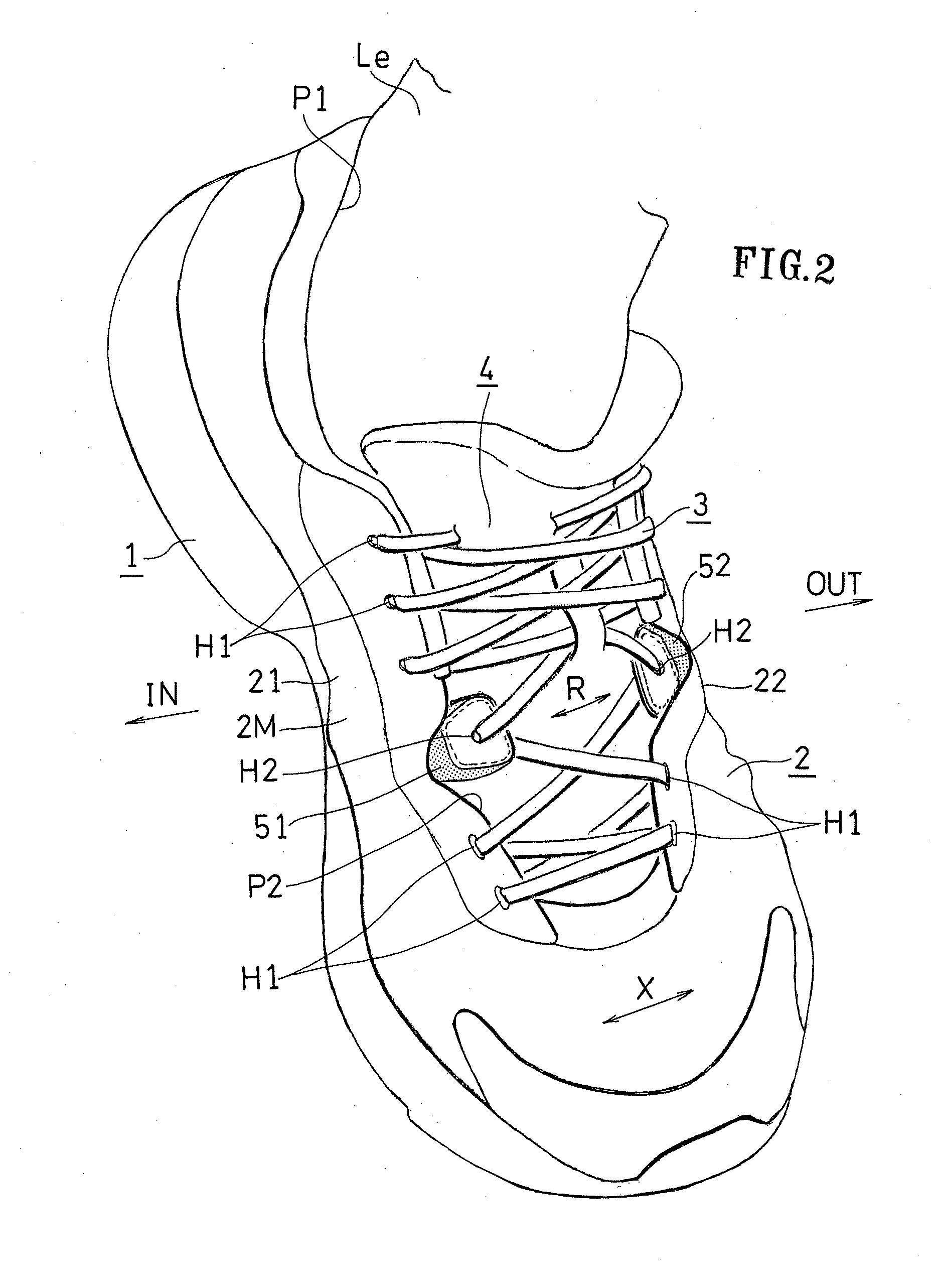
[0150]A shoe for the left foot will be illustrated in the following description. In the following figures, the arrow OUT represents the lateral side direction of the foot, and the arrow IN represents the medial side direction of the foot.

[0151]General Structure of Shoe:

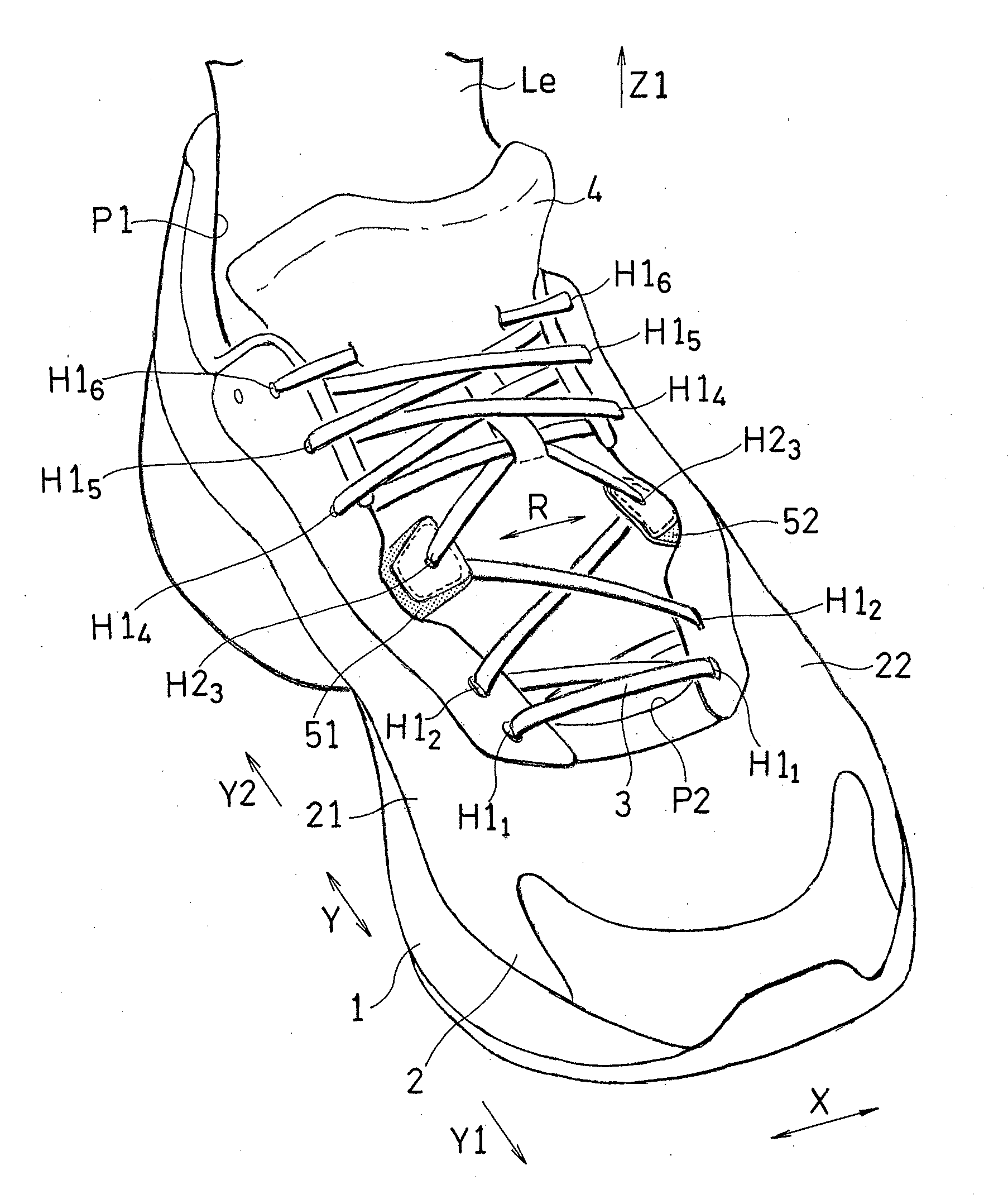
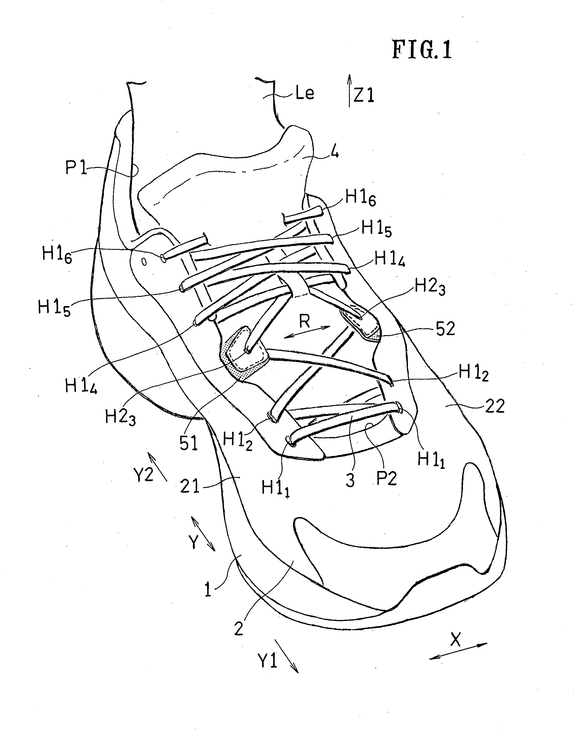
[0152]A shoe having a lace fitting structure shown in FIG. 1 includes a sole 1, an upper 2, and a shoelace 3.

[0153]The sole 1 is for absorbing an impact of landing. The upper 2 is for wrapping around the instep, and includes a tongue 4 (a portion of the main portion). The shoelace 3 is for fitting an upper 2 to the instep.

[0154]Although the end portions of the shoelace 3 are not shown in FIGS. 1 and 2, the end portions are firmly tied together after the foot is inserted into the upper 2. With the end portions of the shoelace 3 tied together, the upper 2 can tightly fit to the foot.

[0155]Note that the end portions of ...

second embodiment

[0184]FIGS. 10 and 11 show a second embodiment.

[0185]In the second embodiment, the main upper 2M includes a bag-like housing 29 for accommodating the middle portion 55 (movable portion) of the side panels 51 and 52. The tip portion 53 of the side panels 51 and 52 protrudes from the housing 29.

[0186]The medial and lateral side surfaces 21 and 22 of the main upper 2M of FIG. 11 are each formed by sewing together a front surface material 23 and a back surface material 24 as shown in FIG. 10. The housing 29 is formed between the two members 23 and 24 sewn together.

[0187]The side panels 51 and 52 are each formed in a band-like shape that conforms to the shape of the housing 29.

[0188]The side panels 51 and 52 may have a stretchable portion including the through holes 55h formed in the middle portion 55, as in the first embodiment, or may be formed by a resin tape having rubber elasticity instead of forming the through holes 55h.

[0189]The term “rubber elasticity” means a property of being...


PUM


Abstract

A shoe having a sole, an upper including a first opening and a second opening, and shoelace means, the upper including: a first side edge portion having a plurality of first eyelets; a second side edge portion arranged between the plurality of first eyelets and having one or more second eyelets which the shoelace means engages with; a movable portion for allowing the second eyelet to move with respect to the first eyelets both in a transverse direction across the second opening and a diagonal front-back direction that is perpendicular to the transverse direction and is extending along the instep; and a main portion covering a medial side surface, a lateral side surface, a toe, the instep and a back surface of a foot, the main portion including the first side edge portion and excluding the second side edge portion and the movable portion; the second eyelet is relatively displaced via the movable portion with respect to the main portion both in the transverse direction and the diagonal front-back direction in response to a change in a direction of a resultant force between a first tensile force and a second tensile force acting upon the second side edge portion from a V-shaped portion of the shoelace means engaging with the second eyelet while transitioning from a flat-footed position to a heel-raised position.

Description

TECHNICAL FIELD[0001]The present invention relates to a shoe having a lace fitting structure.BACKGROUND ART[0002]A shoelace fits an upper to the foot. The upper fitting the foot supports the foot.[0003]However, during dorsal flexion of the MP joint, the foot shape changes, and therefore the foot circumference also changes. When shoes are worn over a long period of time, the foot circumference increases in many cases. In such a case, the foot inside a shoe will be compressed by the upper. Moreover, the shoe and the foot are likely to slip against each other during action.[0004][First Patent Document] Japanese Laid-Open Patent Publication No. 2006-258 (abstract)[0005][Second Patent Document] Japanese Laid-Open Patent Publication No. 11-18803 (abstract)[0006][Third Patent Document] Japanese Utility Model Publication for Opposition No. 33-5240 (FIG. 1)[0007][Fourth Patent Document] Japanese Utility Model Publication for Opposition No. 5-9843 (FIG. 3)[0008][Fifth Patent Document] EPO 329...

Claims


Application Information

Patent Timeline
IPC IPC(8): A43C1/00
CPCA43B7/1495A43B23/027A43C1/003A43C1/00A43C11/008A43B23/0295A43C5/00
Inventor MORIYASU, KENTANISHIWAKI, TSUYOSHINAKAYA, SEIGONAGATA, MOEIKEZAWA, TOMOKO
Owner ASICS CORP
Why Eureka
Try Eureka