
Vehicle door frame and method of producing the same

a technology for door frames and vehicles, applied in the field can solve the problems of thermal distortion of vehicle door frames, congestion of production lines at the stage of welding processes, and deterioration of the operating efficiency of the production lin

Inactive Publication Date: 2012-05-24
SHIROKI KOGYO CO LTD
View PDF21 Cites 5 Cited by
  • Summary
  • Abstract
  • Description
  • Claims
  • Application Information

AI Technical Summary

Benefits of technology

[0007]The present invention has been devised in view of the above described problems of the prior art and provides a vehicle door frame exhibits minimal thermal distortion upon welding and which only requires a short time for the welding process. The present invention further provides a method of producing such a vehicle door frame.
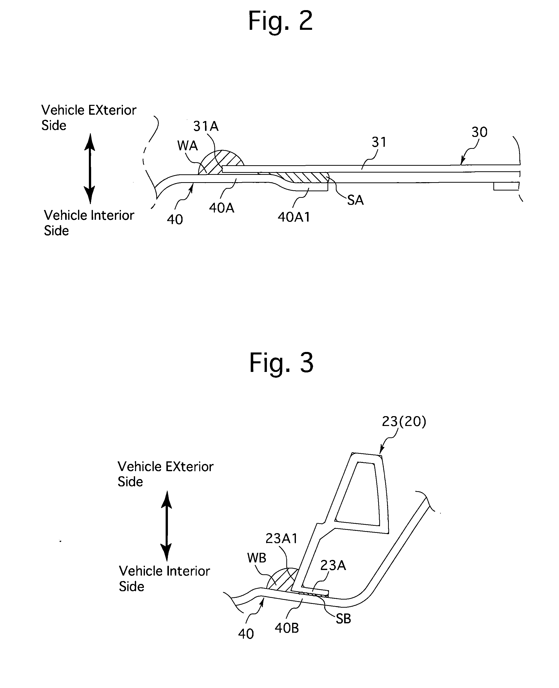
[0012]To overcome such drawbacks, it is desirable that the sash frame and the bracket are each made of a light metallic material, and that the welded portion is formed only on one side of the vehicle door frame (to eliminate the process of turning the sash frame and the bracket which are held traversely (horizontally) at the welding step upside down).
[0014]This structure makes it possible to inject a sufficient amount of adhesive in between opposed surfaces of the sash frame and the bracket, thus making it possible to obtain a joint strength substantially equivalent to that between a sash frame and a bracket which are joined to each other only by welding in a conventional manner.
[0016]By offsetting the adhesion portion and the welded portion in such a manner, the strength of the joint between the sash frame and the bracket can further be increased.
[0022]The step of welding the sash frame and the bracket is performed in the welding process in a factory production line, whereby the sash frame and the bracket are temporarily joined to each other to thereby be positioned relative to each other. The step of injecting a thermosetting adhesive is also performed in the same factory production line after completion of the welding step. By performing the thermosetting-adhesive injecting step after the welding step, accidental ignition of the thermosetting adhesive can be prevented from occurring. In addition, the thermosetting adhesive can be prevented from changing in quality due to welding heat input, and the bonding capability of the thermosetting adhesive can be prevented from deteriorating due to adhesion of spatter or smut to the thermosetting adhesive which occurs when welding is performed. The step of thermally curing the injected thermosetting adhesive can be performed using heat produced for drying paint in a painting process performed in a factory production line, so that no additional process for thermally curing the thermosetting adhesive is required. Alternatively, a heating and curing step for thermally curing the thermosetting adhesive can be provided after the thermosetting-adhesive injecting step.
[0023]According to the present invention, a vehicle door frame which exhibits minimal thermal distortion upon welding and which requires only a short period of time for the welding process can be achieved; and furthermore, a method of producing such a vehicle door frame can be achieved.

Problems solved by technology

Firstly, there is possibility of the vehicle door frame being thermally distorted (strained) if the sash frame and each bracket are joined by welding at an increased number of welding positions to enhance the strength of joint between the sash frame and each bracket.
Secondly, when the times required for a number of the manufacturing processes performed in the production line of a vehicle door frame are mutually compared, it can be seen that the time required for the process of welding the brackets to the sash frame is longer than the time required for any other process, thus causing congestion in the production line at the stage of the welding process.
This congestion increases the entire manufacturing time (Takt time) of the vehicle door frame, thus deteriorating the operating efficiency of the production line.

Method used


Image

  • Vehicle door frame and method of producing the same
  • Vehicle door frame and method of producing the same
  • Vehicle door frame and method of producing the same

Examples


Embodiment Construction

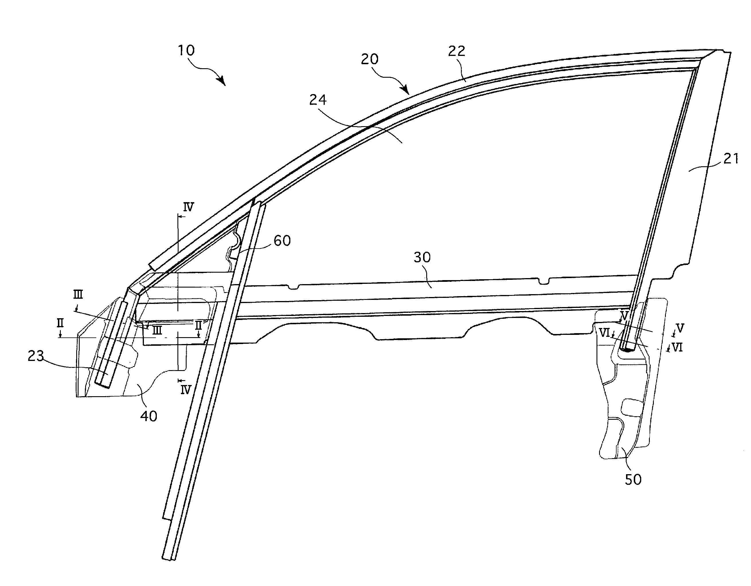
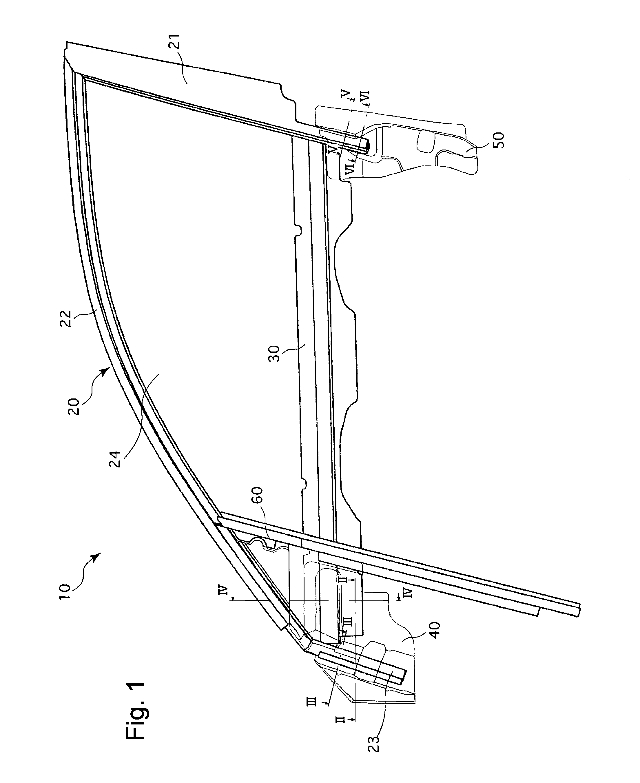
[0033]An embodiment of a door frame (vehicle door frame) 10 made of a light metallic material such as an aluminum alloy, to which a method of producing a vehicle door frame according to the present invention has been applied, will be discussed with reference to FIGS. 1 through 6. The door frame 10 is that of a front door for a front seat of an automobile (vehicle), and the term “forward / rearward direction” in the following descriptions denotes the forward / rearward direction of the door frame 10. However, the present invention can be applied not only to the door frame of a front door for a vehicle front seat but also to the door frame of a rear door for a vehicle rear seat, and even to the door frame of any other door.

[0034]The door frame 10 constitutes a door frame body having an approximately triangular shape which includes a sash frame 20, and a belt-line reinforcing member 30 that is positioned immediately below the sash frame 20 and extends in the forward / rearward direction. The...


PUM


Abstract

A vehicle door frame includes a sash frame that forms a vehicle door frame body and a bracket joined to the sash frame, wherein the sash frame and the bracket are made to mutually overlap each other so that an edge portion of one of the sash frame and the bracket is positioned on the other of the sash frame and the bracket. The sash frame and the bracket are fixed to each other at the edge portion by welding, thereby forming a welded portion thereat. The sash frame and the bracket are fixed to each other by an adhesive injected in between opposed surfaces of the mutually overlapping portions of the sash frame and the bracket, thereby forming an adhesion portion thereat. A method of producing such a vehicle door frame is also disclosed.

Description

BACKGROUND OF THE INVENTION[0001]1. Field of the Invention The present invention relates to a vehicle door frame and a method of producing the vehicle door frame.[0002]2. Description of Related Art[0003]Vehicle door frames are basically provided with a sash frame that forms a vehicle door frame body and two (front and rear) brackets that are respectively joined to the lower front and the lower rear of the sash frame. Conventionally, the sash frame and each bracket have been joined to each other in a mutually overlapping state by welding at a plurality of positions. This conventional structure is disclosed in Japanese Unexamined Patent Publication H11-77320.[0004]However, according to the inventors of the present invention, the above described conventional welding technique, in which the sash frame and each bracket are joined merely by welding, has some problems which will be discussed hereinafter.[0005]Firstly, there is possibility of the vehicle door frame being thermally distorted...

Claims


Application Information

Patent Timeline
IPC IPC(8): B60J5/04
CPCB60J5/0402
Inventor OKADA, TAKAYUKISHIMIZU, KENJIMAKITA, JUNYOKOTA, KAZUYOSHI
Owner SHIROKI KOGYO CO LTD
Learn More