Maintenance system for wind turbine equipment

a maintenance system and wind turbine technology, applied in the direction of machines/engines, mechanical equipment, transportation and packaging, etc., can solve the problems of low efficiency of repair work, insufficient space to ensure, and may require repair, so as to achieve convenient and rapid operation, the effect of optimizing the utilization of the nacell

Active Publication Date: 2012-05-24
DOOSAN HEAVY IND & CONSTR CO LTD
View PDF27 Cites 23 Cited by
  • Summary
  • Abstract
  • Description
  • Claims
  • Application Information

AI Technical Summary

Benefits of technology

[0012]In a maintenance system for wind turbine equipment according to the present invention, a trolley unit is movably provided in a nacelle of the wind turbine equipment, and a winch unit connected to the trolley unit is provided outside the nacelle. When maintenance or repair of an element in the nacelle is required, it can be rapidly and conveniently conducted without using a separate external crane.
[0013]Furthermore, an openable door is provided in the lower surface of the nacelle, so that the element to be maintained or repaired can be removed from or inserted into the nacelle through the door. Thus, space utilization in the nacelle can be optimized.

Problems solved by technology

Particularly, in the case where the wind power generating system is used offshore, abrupt malfunction may be induced by water, salinity, etc., so that an emergency repair may be required.
However, in the conventional technique, a separate large crane is required, or installation of a separate crane in the nacelle is necessary.
Therefore, there are disadvantages in that efficiency of repair work is low, and a sufficiently large space must be ensured on or around the tower.
Moreover, in the conventional technique, the entire upper surface of the nacelle must be opened for maintenance, in other words, a nacelle roof must be opened, thus making the repair work inconvenient and complex.

Method used


Image

  • Maintenance system for wind turbine equipment
  • Maintenance system for wind turbine equipment
  • Maintenance system for wind turbine equipment

Examples


Embodiment Construction

[0018]The above and other objects, features and advantages of the present invention will be more clearly understood from the following detailed description taken in conjunction with the accompanying drawings. Hereinafter, a maintenance system for wind turbine equipment according to a preferred embodiment of the present invention will be described in detail with reference to the attached drawings.

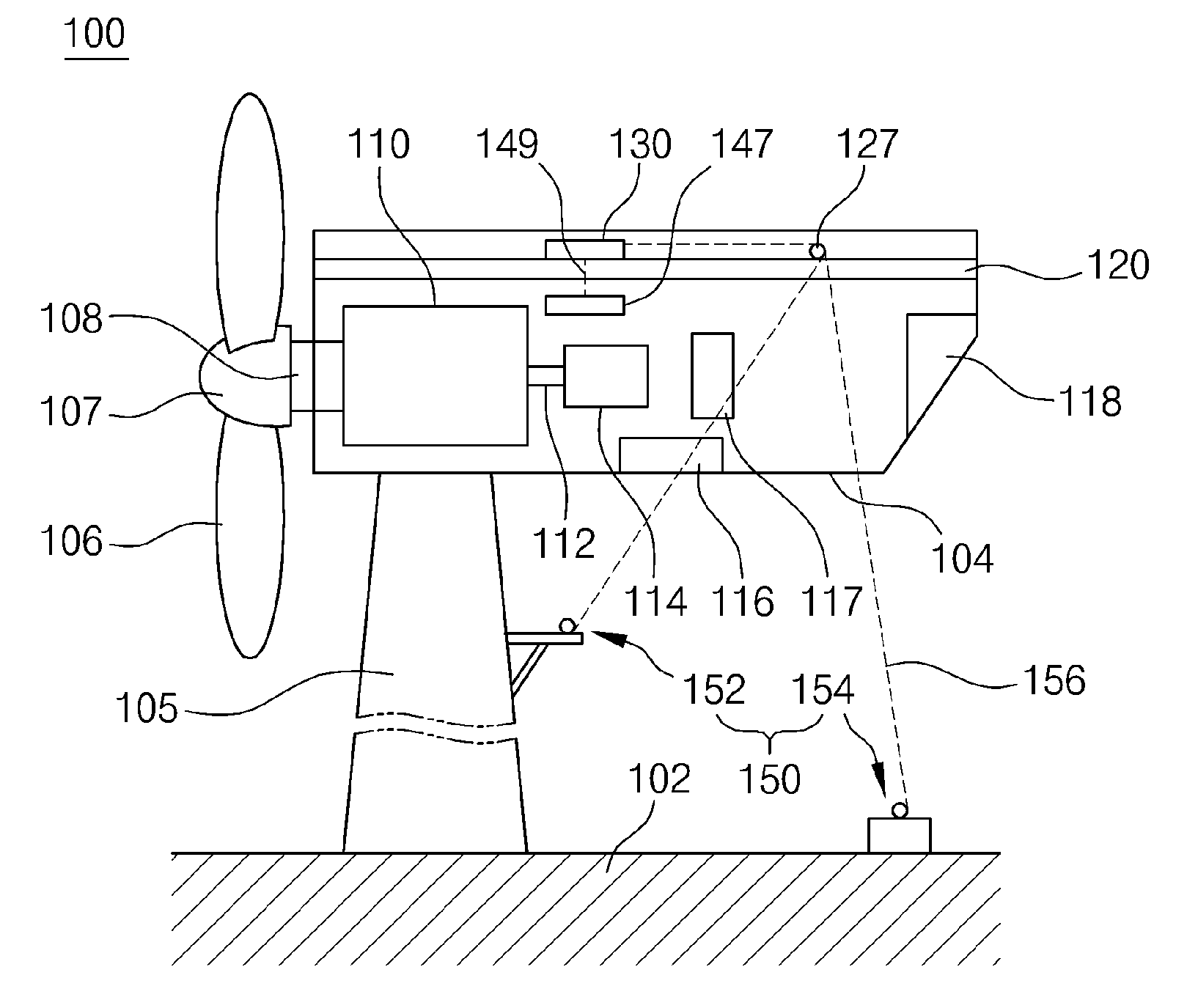
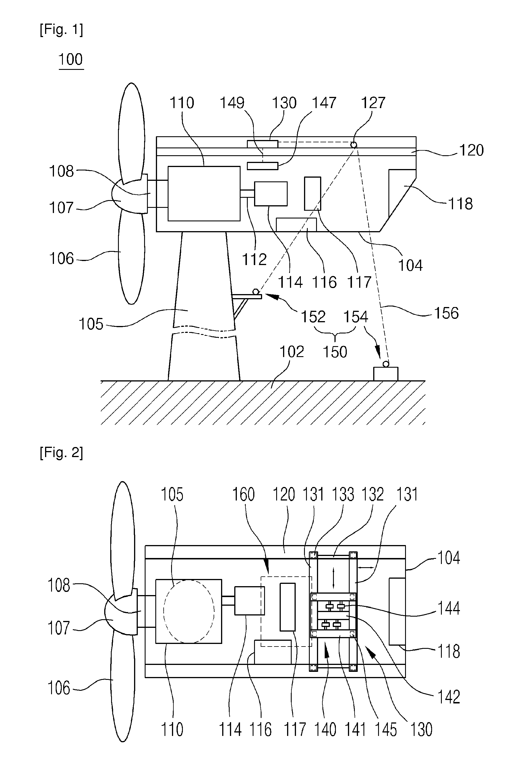
[0019]FIG. 1 is a schematic side view showing the construction of the wind turbine equipment to illustrate the maintenance system for the wind turbine equipment, according to the embodiment of the present invention. FIG. 2 is a plan view showing the construction of a nacelle 104 of the wind turbine to illustrate the maintenance system of FIG. 1 in detail;

[0020]The maintenance system for the wind turbine equipment according to the embodiment of the present invention will be explained with reference to FIGS. 1 and 2.

[0021]As shown in the drawings, the wind turbine equipment 100 includes a towe...


PUM


Abstract

The present invention provides a maintenance system for wind turbine equipment. The maintenance system includes a trolley support unit (130), a trolley (140), a pulley, a winch unit (150) and a door (160). The trolley support unit is provided in the nacelle so as to be movable in the longitudinal direction of the nacelle. The trolley is provided on the trolley support unit so as to be movable in the lateral direction of the nacelle. The pulley is rotatably installed in the trolley. The winch unit is connected to the pulley through a wire. The door is provided in the nacelle so that an element of the nacelle to be repaired is removed from or inserted into the nacelle through the door. Therefore, in the present invention, when maintenance or repair of an element in the nacelle is required, it can be conveniently conducted without using a separate crane.

Description

TECHNICAL FIELD [0001]The present invention relates, in general, to maintenance systems for wind turbine equipment and, more particularly, to a maintenance system for wind turbine equipment which is constructed such that when maintenance or repair of an element in a nacelle of the wind turbine equipment is required, the maintenance or repair can be easily and efficiently conducted.BACKGROUND ART [0002]Generally, wind power generating systems convert kinetic energy created by wind into electric energy. According to the installation place, the wind power generating system is classified into an onshore system or an offshore system.[0003]Typically, such a wind power generating system includes a tower which is supported on supporting ground, a nacelle which is provided on the upper end of the tower, and a blade which is coupled to the front end of the nacelle. The nacelle has therein several devices, such as a gear box, a generator, an inverter, etc., which are necessary to generate elec...

Claims


Application Information

Patent Timeline
Patent Type & Authority Applications(United States)
IPC IPC(8): F03D11/00B66C17/26
CPCF03D1/003F05B2240/916Y02E10/726B66C17/00Y02E10/721F05B2250/43Y02E10/728B66C17/04B66C23/207F03D80/50Y02E10/72F03D13/20F05B2230/80
Inventor PARK, HYUN YONGPARK, JONG POPARK, JUNG HUNLEE, JEONG HOONKIM, JEONG ILLEE, BYUNG KYU
Owner DOOSAN HEAVY IND & CONSTR CO LTD
Why Eureka
Try Eureka