Discharge device and electrostatic atomization device comprising same

Inactive Publication Date: 2012-05-24
PANASONIC CORP
View PDF0 Cites 33 Cited by
  • Summary
  • Abstract
  • Description
  • Claims
  • Application Information

AI Technical Summary

Benefits of technology

[0009]The present invention provides a discharge device capable of stably and efficiently generating a discharge product by suppressing oscillation of a piezoelectric oscillator and an electrostatic atomization device including such a discharge device.
[0010]One aspect of the present invention is a discharge device. The discharge device includes a power supply unit that supplies a first voltage, a piezoelectric oscillator that oscillates to increase the first voltage to a second voltage, and a first electrode that performs discharging based on the second voltage to generate a discharge product. The first electrode and the piezoelectric oscillator are arranged out

Problems solved by technology

However, a piezoelectric oscillator has a drawback in that mechanical oscillation (ultrasonic oscillation) is generated.
Accordingly, the conv

Method used


Image

  • Discharge device and electrostatic atomization device comprising same
  • Discharge device and electrostatic atomization device comprising same
  • Discharge device and electrostatic atomization device comprising same

Examples


Example

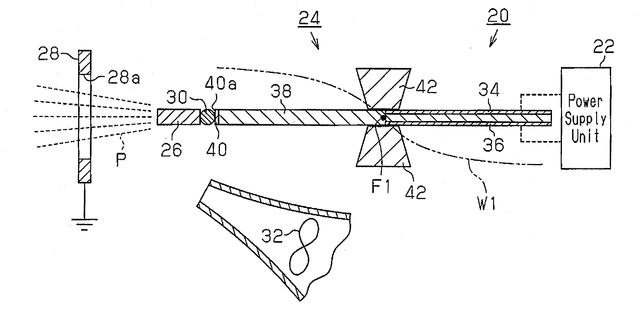
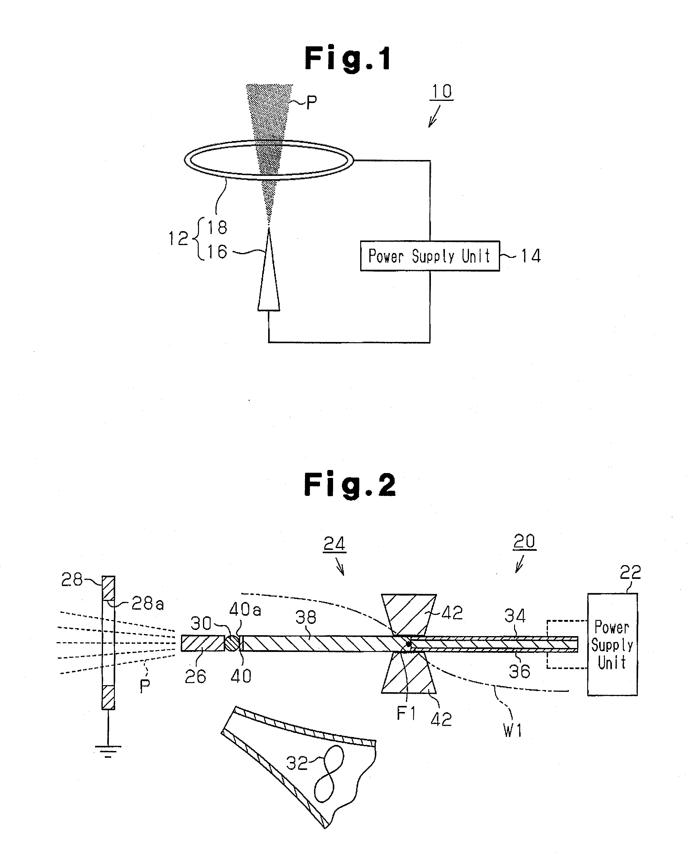
[0047]A discharge device 20 according to a first embodiment will now be described with reference to FIGS. 2 to 5. For example, the discharge device 20 according to the first embodiment is applied to a metal microparticle generator installed in a hair drier to generate metal microparticles as a discharge product P.

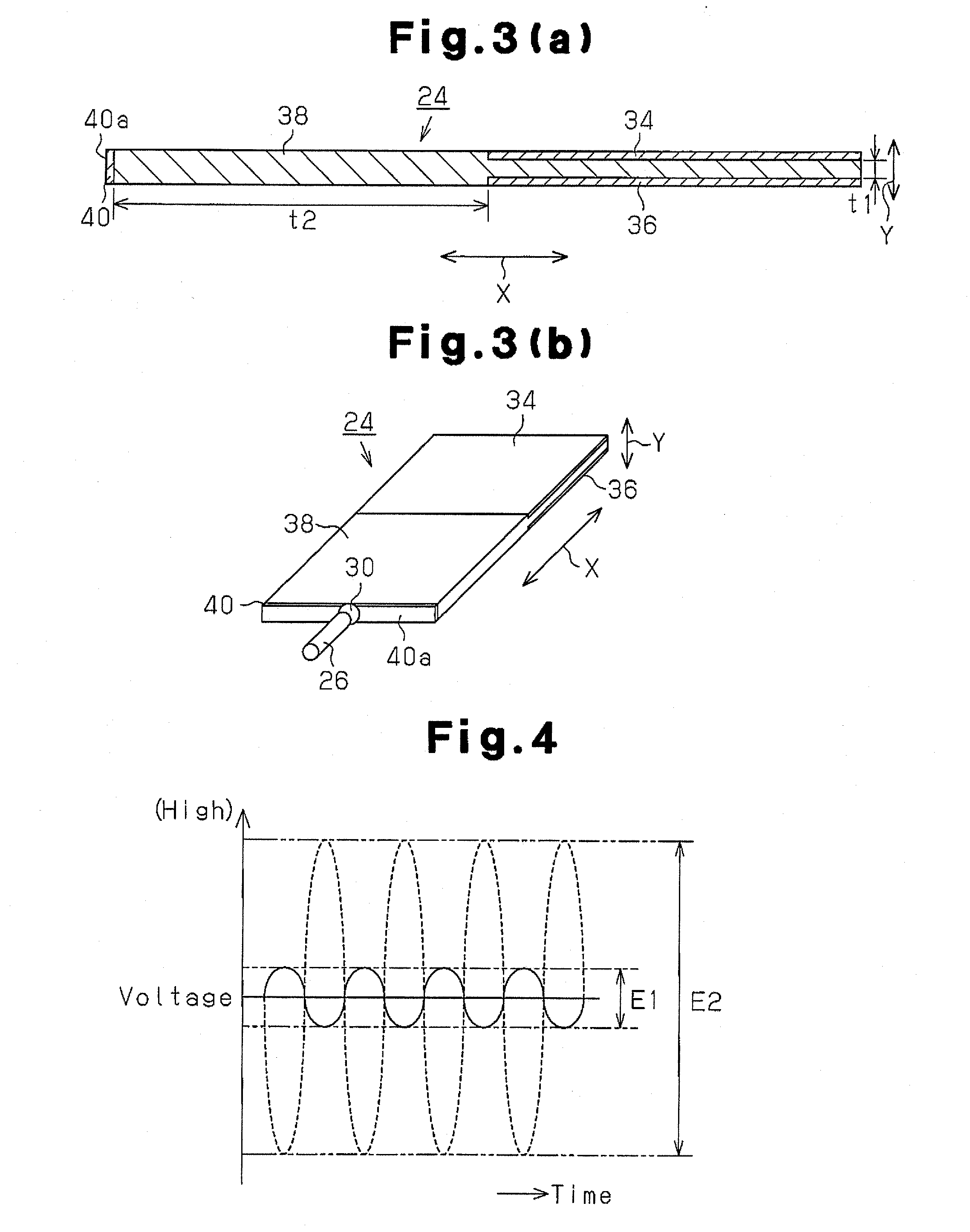
[0048]As shown in FIG. 2, the discharge device 20 includes a power supply unit 22, which supplies a first voltage (e.g., an AC voltage from a commercial power supply) as power, a piezoelectric oscillator 24 (i.e., a piezoelectric transformer) that oscillates to increase the first voltage to a second voltage (AC voltage), and a discharge electrode 26, which serves as a first electrode that performs discharging upon application of the increased second voltage.

[0049]The discharge device 20 further includes an opposing electrode 28, which serves as a second electrode that is spaced apart from the discharge electrode 26. The second voltage is applied between the opposing electro...

Example

Second Embodiment

[0085]A discharge device 50 according to a second embodiment will now be described with reference to FIG. 8. The discharge device 50 according to the second embodiment is applied to an electrostatic atomization device 51 and generates charged microparticle mist (charged atomized liquid) as a discharge product P. In the structure of the second embodiment, components similar to those in the first embodiment are denoted by the same reference characters.

[0086]As shown in FIG. 8, the discharge device 50 in the electrostatic atomization device 51 includes a power supply unit 22, which that supplies AC voltage (first voltage), a piezoelectric oscillator 24, which increases the first voltage to a second voltage, and a discharge electrode 52, which serves as a first electrode. The discharge device 50 further includes a contact member 54, which is arranged between the discharge electrode 52 and the piezoelectric oscillator 24 and which serves as an oscillation attenuation uni...

Example

Third Embodiment

[0115]A discharge device 80 according to a third embodiment will now be described with reference to FIG. 15. The discharge device 80 according to the third embodiment is also applied to an electrostatic atomization device 82 and generates ions or a charged microparticle mist as a discharge product P. The discharge device 80 according to the third embodiment has the same structure as the discharge device 50 according to the second embodiment (FIG. 8). In the structure of the third embodiment, components similar to those in the first and second embodiments are denoted by the same reference characters.

[0116]As shown in FIG. 15, the electrostatic atomization device 82 includes the discharge device 80 and a humidity environment formation unit 84. The humidity environment formation unit 84 is arranged in a discharge zone 86 in which a discharge electrode 52 performs discharging to generate charged microparticles (the discharge product P), and forms a humidity environment u...


PUM


Abstract

Disclosed is a discharge device (20) which comprises a power supply unit (22) that supplies a first voltage, a piezoelectric transducer (24) that increases the first voltage to a second voltage by means of vibrations, and a first electrode (26) for producing a discharge product (P) by performing a discharge upon application of the second voltage. The first electrode (26) and the piezoelectric transducer (24) are electrically connected with each other via a vibration damping unit (30). In other words, the first electrode (26) and the piezoelectric transducer (24) are arranged to be out of contact with each other.

Description

TECHNICAL FIELD[0001]The present invention relates to a discharge device and an electrostatic atomization device including the discharge device.BACKGROUND ART[0002]In recent years, discharge devices have been widely applied to various products. For example, discharge devices are built into air conditioners as ion generators that are discharged to emit negative ions. As another example, discharge devices are also used as metal microparticle generators that emit metal microparticles by sputtering a metal electrode with discharge ions. Patent Document 1 describes hair drier including such a metal microparticle generator that decomposes reactive oxygen, which is generated by ultraviolet rays, with an antioxidative effect produced by platinum microparticles in order to reduce damage to hair. In addition, as described in Patent Document 2, a discharge device is also used as an electrostatic atomization device that generates mist containing charged microparticles by electrostatically atomi...

Claims


Application Information

Patent Timeline
IPC IPC(8): B05B5/025H02N2/00
CPCA45D20/08B05B5/0531Y02B30/80B05B17/0638F24F2006/125B05B5/057Y02B30/70
Inventor NUNOMURA, MAHITOSUDA, HIROSHIMISHIMA, YUKIKOMACHI, MASAHARUOE, JUNPEIKOMURA, YASUHIROASANO, YUKIYASUKITAMURA, HIROYASUIZUMI, TOMOHIRO
Owner PANASONIC CORP
Why Eureka
Try Eureka