Concentric motor power generation and drive system

a technology of concentric motors and drive systems, applied in the direction of dynamo-electric converter control, propulsion by batteries/cells, transportation and packaging, etc., can solve the problems of relatively heavy vehicles and less fuel economical than

a technology of concentric motors and drive systems, applied in the direction of dynamo-electric converter control, propulsion by batteries/cells, transportation and packaging, etc., can solve the problems of relatively heavy vehicles and less fuel economical than

US20120126650A1Active Publication Date: 2012-05-24BORGWARNER INC

Image

  • Concentric motor power generation and drive system
  • Concentric motor power generation and drive system
  • Concentric motor power generation and drive system

Examples


Embodiment Construction

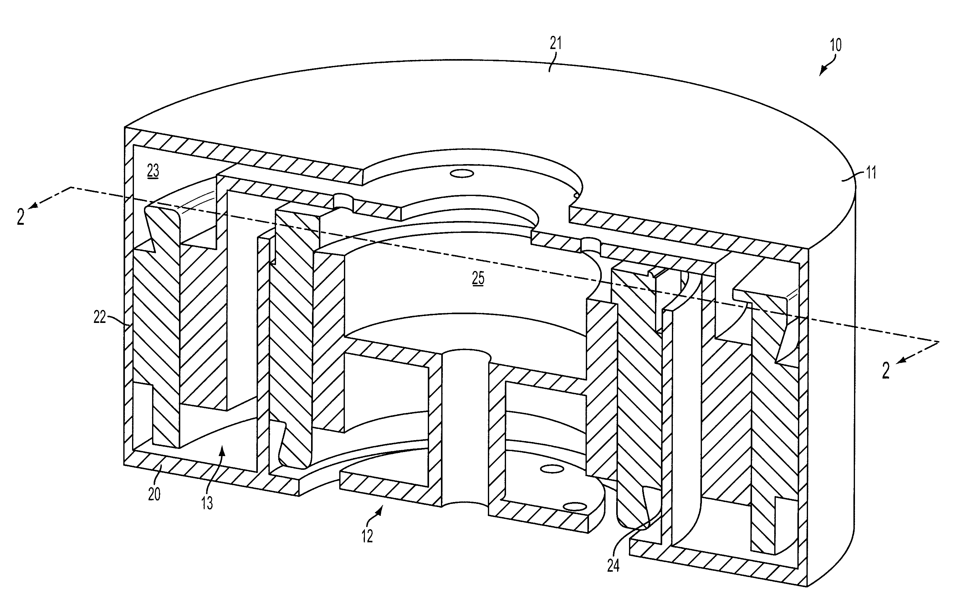
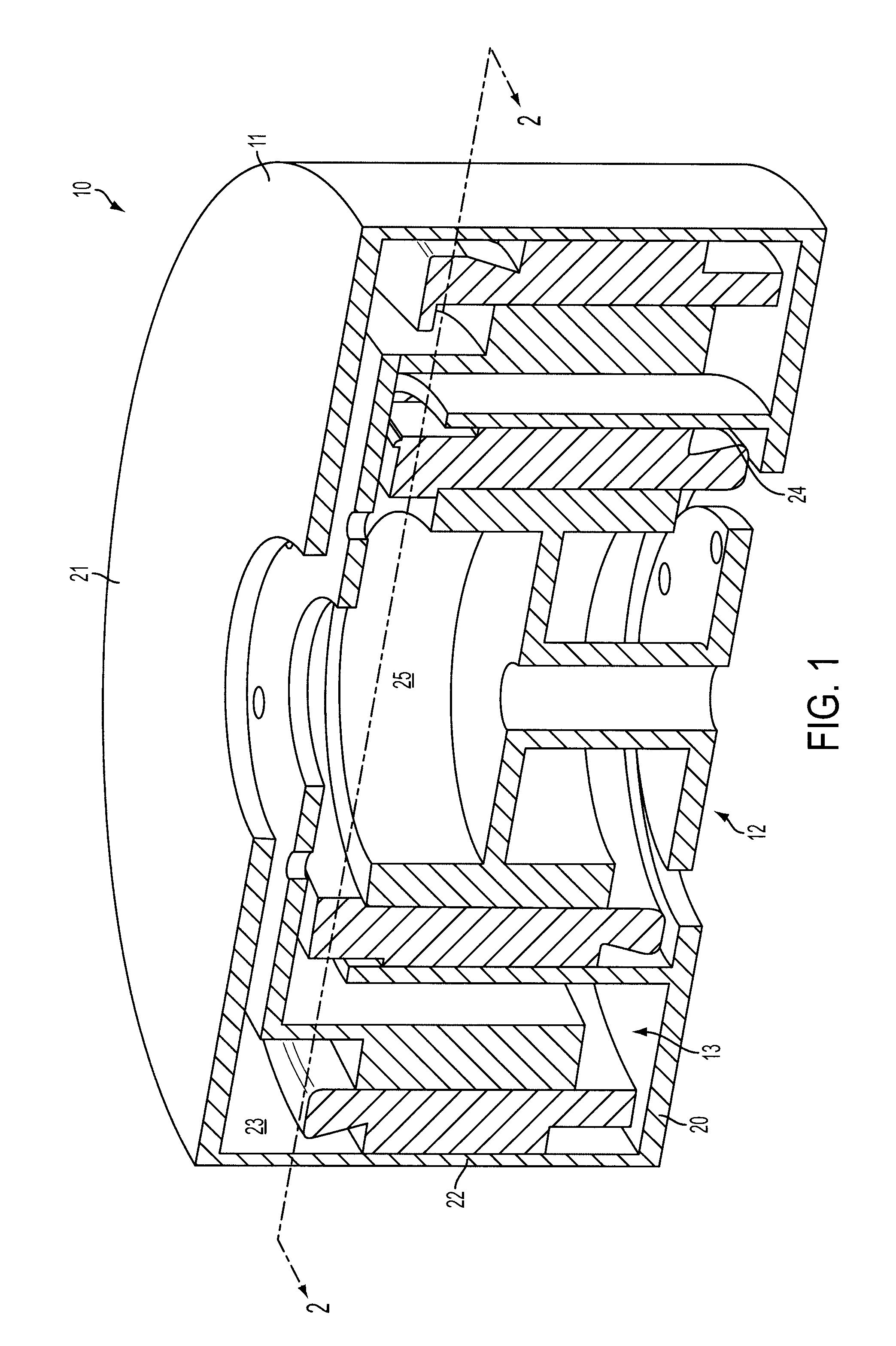
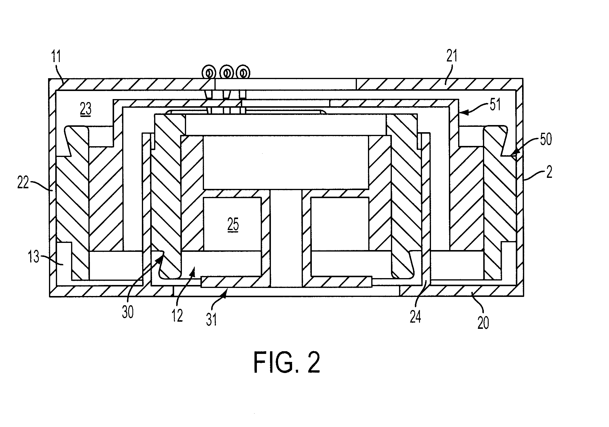
[0016]With reference to FIGS. 1-3, a concentric motor power generation and drive system apparatus 10 is provided. The apparatus 10 includes a hub 11, a first assembly 12 and a second assembly 13. The hub 10 includes first and second opposing faces 20, 21, a first sidewall 22 fixed at opposite ends thereof to the first and second opposing faces 20, 21 to define a first interior 23 between the first and second opposing faces 20, 21 and a second sidewall 24. The second sidewall 24 is fixed to one of the first and second opposing faces 20, 21 to define a second interior 25 within the first interior 23. The hub 10 may therefore be a housing and may be rigidly affixed to an engine, a drive power generation device or some similar type of mounting.

[0017]The first assembly 12 is disposed within the second interior 25 and is configured to generate electrical current from input mechanical energy. By contrast, the second assembly 13, which is electrically coupled to the first assembly 12, is di...


PUM


Abstract

An apparatus is provided and includes a hub, including first and second opposing faces, a first sidewall fixed at opposite ends thereof to the first and second opposing faces to define a first interior between the first and second opposing faces and a second sidewall fixed to one of the first and second opposing faces to define a second interior within the first interior, a first assembly, disposed within the second interior, to generate current from input mechanical energy and a second assembly, electrically coupled to the first assembly and disposed within the first interior, to generate mechanical energy from current associated with the current generated by the first assembly.

Description

BACKGROUND OF THE INVENTION[0001]The subject matter disclosed herein relates to a concentric motor power generation and drive system.[0002]In many vehicles and, in particular, hybrid vehicles, power transmission systems are used for converting mechanical energy generated in an engine into electrical energy that can either be stored or converted back to mechanical energy that can be employed for driving purposes. These power transmission systems often include a generator rotor, which is driven to rotate by a drive shaft that is rotatably coupled to an engine, and a generator stator, which converts the rotor rotation into electrical energy. This electrical energy is either stored by a battery or transmitted to a drive stator, which induces rotation of a drive rotor that is, in turn, coupled to, for example, vehicle wheels.[0003]Typically, in conventional power transmission systems, the generator elements and the drive elements are not mounted together and may be, in fact, disposed at ...

Claims


Application Information

Patent Timeline
24 May 2012
Publication
US20120126650A1
IPC
H02K47/00
CPC
B60K7/0007; H02K51/00; Y02T10/7077; Y02T10/641; Y02T10/6217; H02K47/00; H02K47/04; H02K47/14
Inventors
KUBES, LARRY; FULTON, DAVID