Liquid feed valve unit and liquid ejection device

a technology of liquid feed valve and liquid ejection device, which is applied in printing and other directions, can solve the problem of time-consuming operation, and achieve the effect of short tim

Active Publication Date: 2012-05-24
SEIKO EPSON CORP
View PDF20 Cites 25 Cited by
  • Summary
  • Abstract
  • Description
  • Claims
  • Application Information

AI Technical Summary

Benefits of technology

[0024]According to this aspect, since the device control unit implements the blocking mode in the liquid feed valve unit in a case in which the inside of the liquid ejection head is suct...

Problems solved by technology

Problems therefore arise in that it is necessary to wait until the residual pr...

Method used


Image

  • Liquid feed valve unit and liquid ejection device
  • Liquid feed valve unit and liquid ejection device
  • Liquid feed valve unit and liquid ejection device

Examples


Embodiment Construction

[0034]Embodiments of the present invention will be described with reference to the drawings.

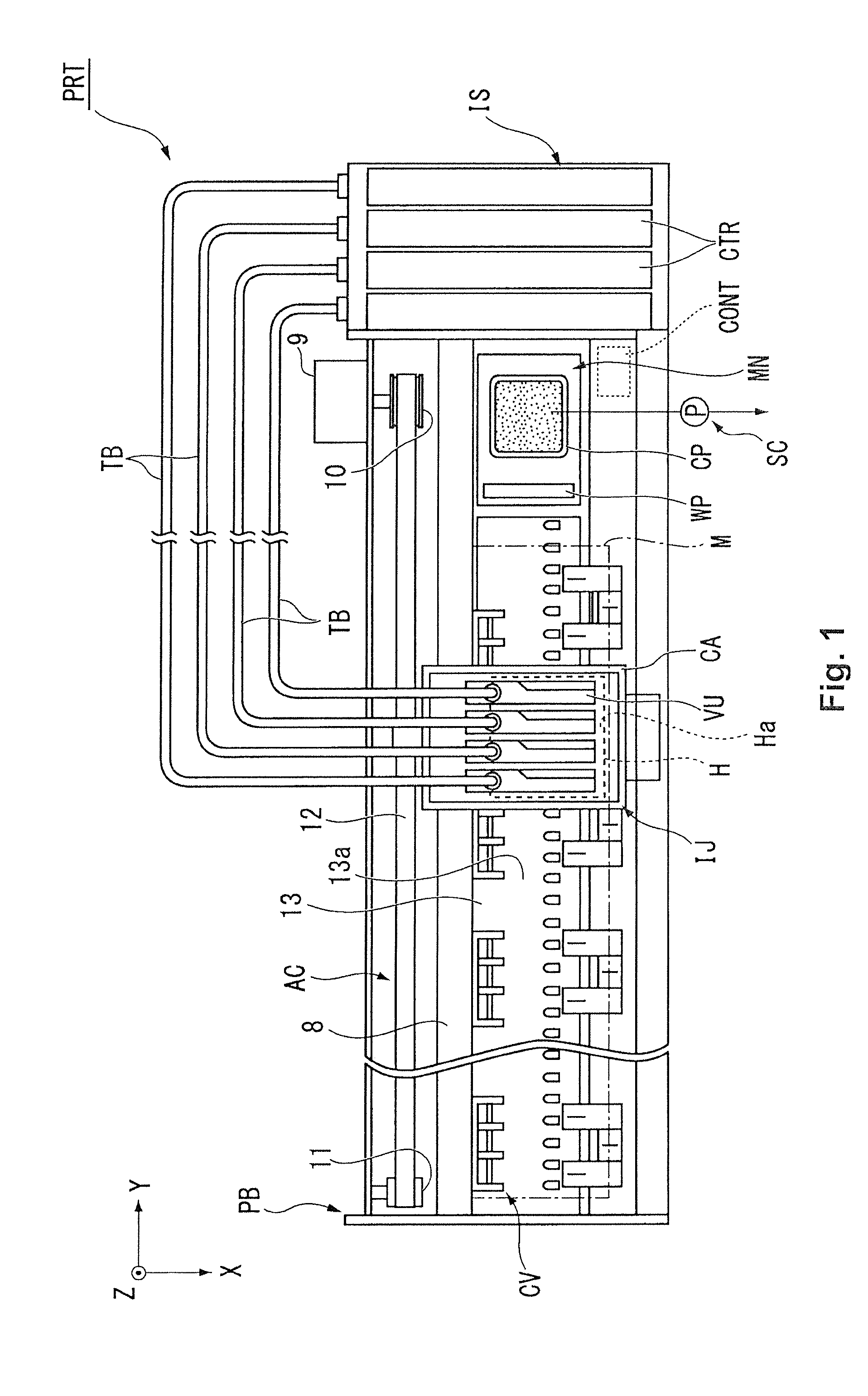
[0035]FIG. 1 is a view showing the overall configuration of the printing device PRT (liquid ejection device) according to the present embodiment. In the present embodiment, an inkjet-type printing device will be described as an example of the printing device PRT.

[0036]The printing device PRT shown in FIG. 1 is a device for performing print processing while conveying a paper, plastic sheet, or other sheet-shaped medium M. The printing device PRT is provided with a housing PB; an inkjet mechanism IJ for ejecting ink to the medium M; an ink feeding mechanism IS for feeding the ink to the inkjet mechanism IJ; a conveyance mechanism CV for conveying the medium M; a maintenance mechanism MN for performing maintenance of the inkjet mechanism IJ; and a control device CONT for controlling each mechanism.

[0037]An XYZ orthogonal coordinate system is set up for the following description, and the position...


PUM


Abstract

A liquid feed valve unit is configured to switch between a releasing mode for forcibly opening a valve and a blocking mode for closing the valve, and the valve can therefore be opened and closed in a short time as needed. Since the releasing mode is implemented by pushing the peripheral part and the pressure-receiving part of the flexible member, the flexible member can be prevented from flexing toward the outside of the liquid accommodating chamber even in the case that the pressure-receiving part is pushed. In this case, since a residual pressure can be prevented from forming in the liquid accommodating chamber, there is no need to suspend operation, and it is possible to immediately proceed to the next operation. A fast-operating liquid feed valve unit can thereby be obtained.

Description

CROSS-REFERENCE TO RELATED APPLICATIONS[0001]This application claims priority to Japanese Patent Application No. 2010-259180 filed on Nov. 19, 2010. The entire disclosure of Japanese Patent Application No. 2010-259180 is hereby incorporated herein by reference.BACKGROUND[0002]1. Technical Field[0003]The present invention relates to a liquid feed valve unit and a liquid ejection device.[0004]2. Related Art[0005]Inkjet printing devices (hereinafter referred to as “printing devices”), for example, and the like are known as liquid ejection devices for ejecting a liquid. A printing device is a device for recording characters, images, and the like on a recording medium. A printing device is configured so that ink is ejected to a recording medium from a nozzle provided to an ejection head. The ejection head is mounted to a carriage, for example, or other movement mechanism, and is configured so as to eject ink while moving over the recording medium.[0006]In a printing device of the type re...

Claims


Application Information

Patent Timeline
IPC IPC(8): B41J2/175
CPCB41J2/175B41J2/17596B41J2/17509
Inventor KOIKE, KAORUKUMAGAI, TOSHIOSHIMIZU, KAZUTOSHI
Owner SEIKO EPSON CORP
Why Eureka
Try Eureka