Method And Apparatus For Displaying 3D Images

a technology of 3d images and methods, applied in the field of methods and apparatus for displaying 3d images, can solve the problems of uneven total intensity, weak limit of the performance of such systems, and the inability of the apparatus to display images with sharp contours

Active Publication Date: 2012-05-24
BALOGH
View PDF3 Cites 70 Cited by
  • Summary
  • Abstract
  • Description
  • Claims
  • Application Information

AI Technical Summary

Problems solved by technology

However, it is a general problem in the prior art solutions that in the process of changing a viewer's position in the 3D light-field, depending on the physical adjustments of the projectors, the diffusion angle of the screen, the optical imperfections, distortions, geometrical or color misalignments, and / or brightness / contrast differences between the projectors, the viewer (observer) will perceive a fluctuation of the intensity, i.e. inhomogeneities will appear at the transitions between two 3D images.
For the observer the perceived image will then be blurred, the neighboring views will be simultaneously present in the 3D image and the apparatus will not be capable of displaying images with sharp contours.
Furthermore, the screen diffusion characteristic is a critical factor in such systems, and unfortunately, this Gaussian intensity distribution is inherent in all practical diffusers even in holographic diffusion screens.
The uneven total intensity or the undesirable crosstalk is practically unavoidable since these are conflicting requirements; this fact strongly limits the performance of such systems.
If the systems are not finely calibrated, serious alignment, color dispersion problems can arise, which again cause a deterioration of the perceived image.

Method used


Image

  • Method And Apparatus For Displaying 3D Images
  • Method And Apparatus For Displaying 3D Images
  • Method And Apparatus For Displaying 3D Images

Examples


first embodiment

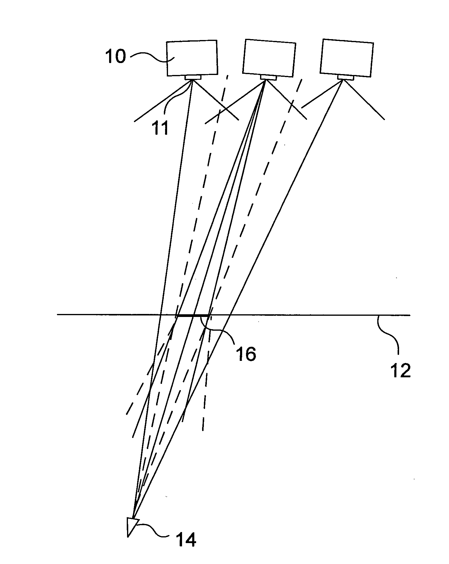
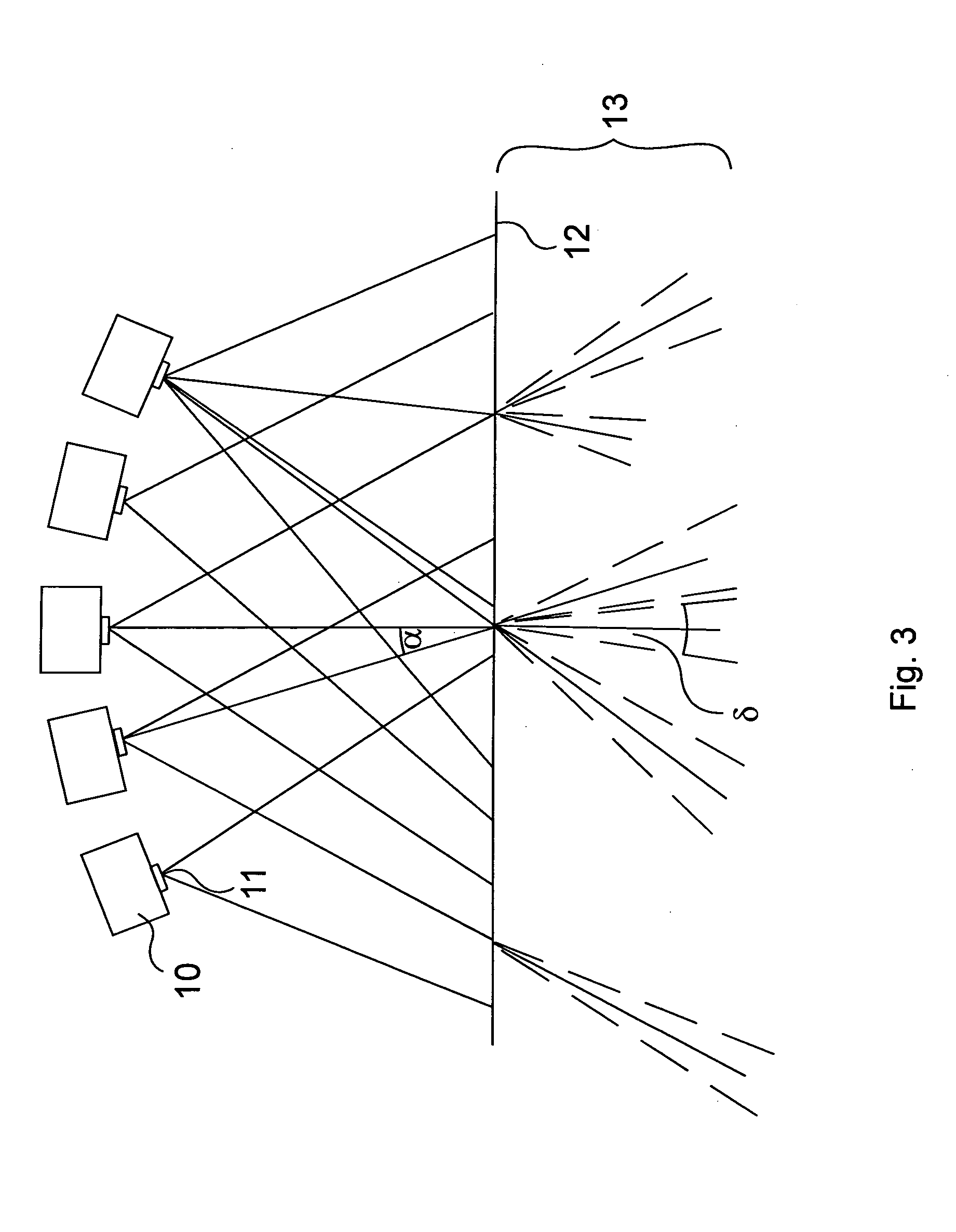
[0008]FIG. 3 is a schematic diagram of the inventive apparatus,

[0009]FIG. 4 is a schematic diagram depicting the functioning of the embodiment as of FIG. 3,

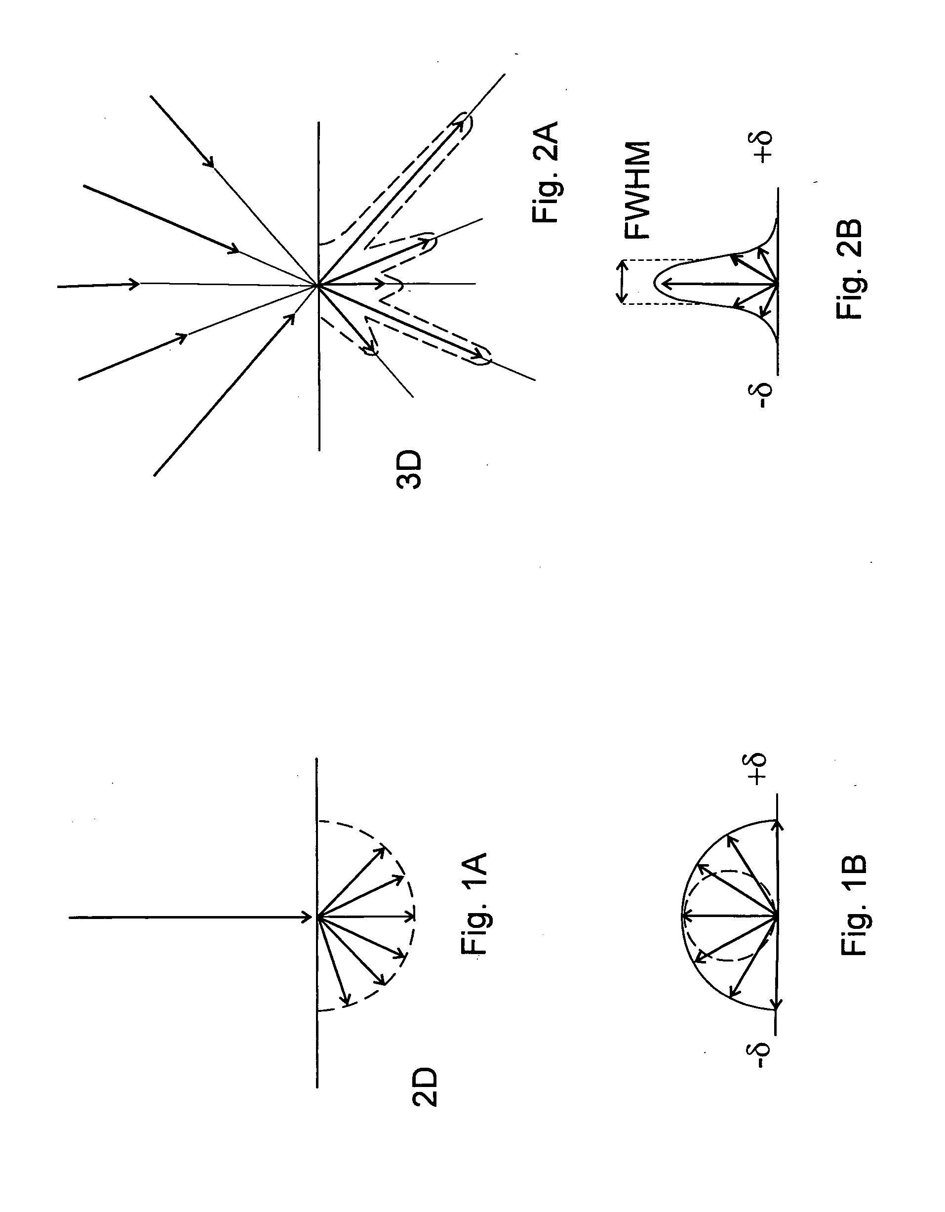
[0010]FIGS. 5A and 5B are schematic diagrams depicting vertical segments of the displaying mechanism of the preferred embodiment as of FIG. 3,

[0011]FIG. 6 is a schematic view of a preferred back-projection embodiment of the apparatus with a calibration device,

[0012]FIGS. 7A-7C are schematic views of a front-projection embodiment used in a 3D cinema,

[0013]FIGS. 8A and 8B are schematic drawings of the view area with a curved mirror-like reflective screen and a retroreflective screen, respectively,

[0014]FIG. 8C is a preferred retroreflective screen structure,

[0015]FIG. 9 is a schematic diagram of the inventive apparatus with a curved screen,

fourth embodiment

[0016]FIGS. 10A and 10B are schematic views of a fourth embodiment used in a PDA device,

fifth embodiment

[0017]FIG. 11 is a schematic view of a fifth embodiment used in a mini laptop device,


PUM


Abstract

A method and an apparatus for displaying 3D images are disclosed. 2D images are projected from multiple points to a surface with narrow diffusion characteristics, thus it is possible to get a 3D light field with arbitrary angular dependence. According to the invention, the projectors (10) do not target particular screen (12) points. The projectors (10) are directed to the screen (12) with no special positioning, however from the bunch of light beams present, pertaining to the large number of pixels in the projected images, it is possible to select and define a pixel-wise precise 3D light-field through a calibration process. A novel calibration method and device are also described for calibrating 3D display systems, the device being equipped with proper image sensor(s) and a control system.

Description

TECHNICAL FIELD[0001]The invention relates to a method and an apparatus for displaying 3D images, as well as to a method and a device for calibrating the apparatus.BACKGROUND ART[0002]Methods and systems for generating 3D images are disclosed e.g. in WO 01 / 88598 A2, WO 2005 / 117458 A2, the teachings of which are incorporated by reference. The known apparatuses comprise multiple optical modules projecting light beams onto a diffuser screen, thus with proper control, light beams of different color and intensity are propagating from each point of the screen, reconstructing a 3D light field. As a viewer is changing her / his position in the 3D light-field, the perceived 3D image changes accordingly, thereby a true 3D, real life effect is provided.[0003]However, it is a general problem in the prior art solutions that in the process of changing a viewer's position in the 3D light-field, depending on the physical adjustments of the projectors, the diffusion angle of the screen, the optical im...

Claims


Application Information

Patent Timeline
Patent Type & Authority Applications(United States)
IPC IPC(8): H04N17/00G06T15/00G02B27/22G06F3/038G02B30/27
CPCG02B5/0257G02B5/0278H04N13/0459G02B27/2214H04N13/0425G02B5/0284H04N13/363H04N13/327G02B30/27
Inventor BALOGH
Owner BALOGH
Why Eureka
Try Eureka