Welding structural part and welding method of the same

a technology of structural parts and welding methods, applied in welding/soldering/cutting articles, manufacturing tools, transportation and packaging, etc., to achieve the effect of high fracture strength, strong and tough spot weld zon

Inactive Publication Date: 2012-05-24
NETUREN CO LTD +1
View PDF10 Cites 24 Cited by
  • Summary
  • Abstract
  • Description
  • Claims
  • Application Information

AI Technical Summary

Benefits of technology

[0039]According to the present invention, a welding structural part having a highly strong and tough spot weld zone, and high fracture strength confirmed by a cross tensile test, and a method of welding can be provided.

Problems solved by technology

Since the generation of the sputter 56 may result in defects in the painting process to be conducted after the spot welding, it is undesirable.

Method used


Image

  • Welding structural part and welding method of the same
  • Welding structural part and welding method of the same
  • Welding structural part and welding method of the same

Examples


example 1

[0155]Specific examples where steel sheets 2 are spot welded by the welding equipment 10 will hereinafter be described in detail.

[0156]Two steel sheets 2 were spot-welded. The conditions including the steel sheets 2, the low-frequency power supply 16, and the high-frequency power supply 18 used are shown below.[0157]Steel sheets 2: Thickness; 1.2 mm, Size; 5 cm×15 cm[0158]Low-frequency power supply 16: 50 Hz; Electrodes 14 made of copper has tip diameter of 6 mm and; Power capacity of 50 kVA[0159]Energization time of low-frequency power supply 16: 0.3 to 0.5 sec[0160]High-frequency power supply 18: 30 kHz; 50 kW output[0161]Energization time of high-frequency power supply 18: 0.3 to 0.6 sec

[0162]Composition of the steel sheets 2 includes C (carbon) in 0.19 to 0.29 mass % other than iron.

[0163]FIG. 12 is a chart illustrating the application of the power from the low-frequency power supply 16 and high-frequency power supply 18 in Example 1.

[0164]At first, the welding was performed by ...

example 2

[0165]In Example 2, the high-frequency power of 16 kW was applied for 0.3 sec. or 0.6 sec. The power from the low-frequency power supply 6 was applied in the same manner as Example 1.

example 3

[0166]In Example 3, the high-frequency power of 27 kW was applied for 0.3 sec. or 0.6 sec. The power from the low-frequency power supply 6 was applied in the same manner as Example 1.


PUM

PropertyMeasurementUnit
particle diameteraaaaaaaaaa
particle volume fractionaaaaaaaaaa
breaking forceaaaaaaaaaa

Abstract

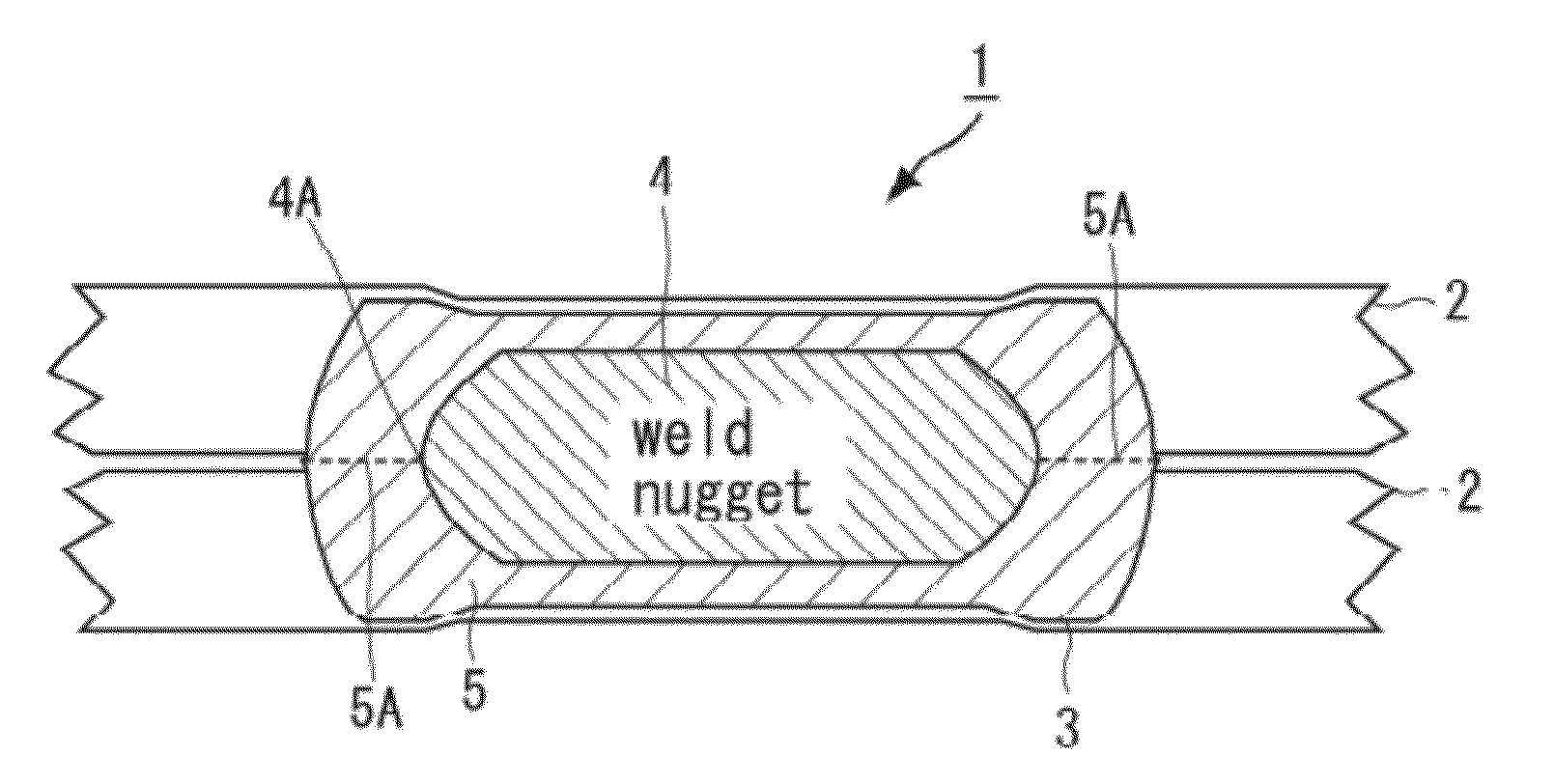
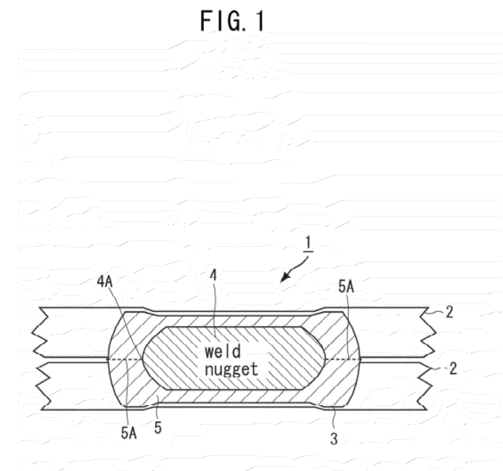
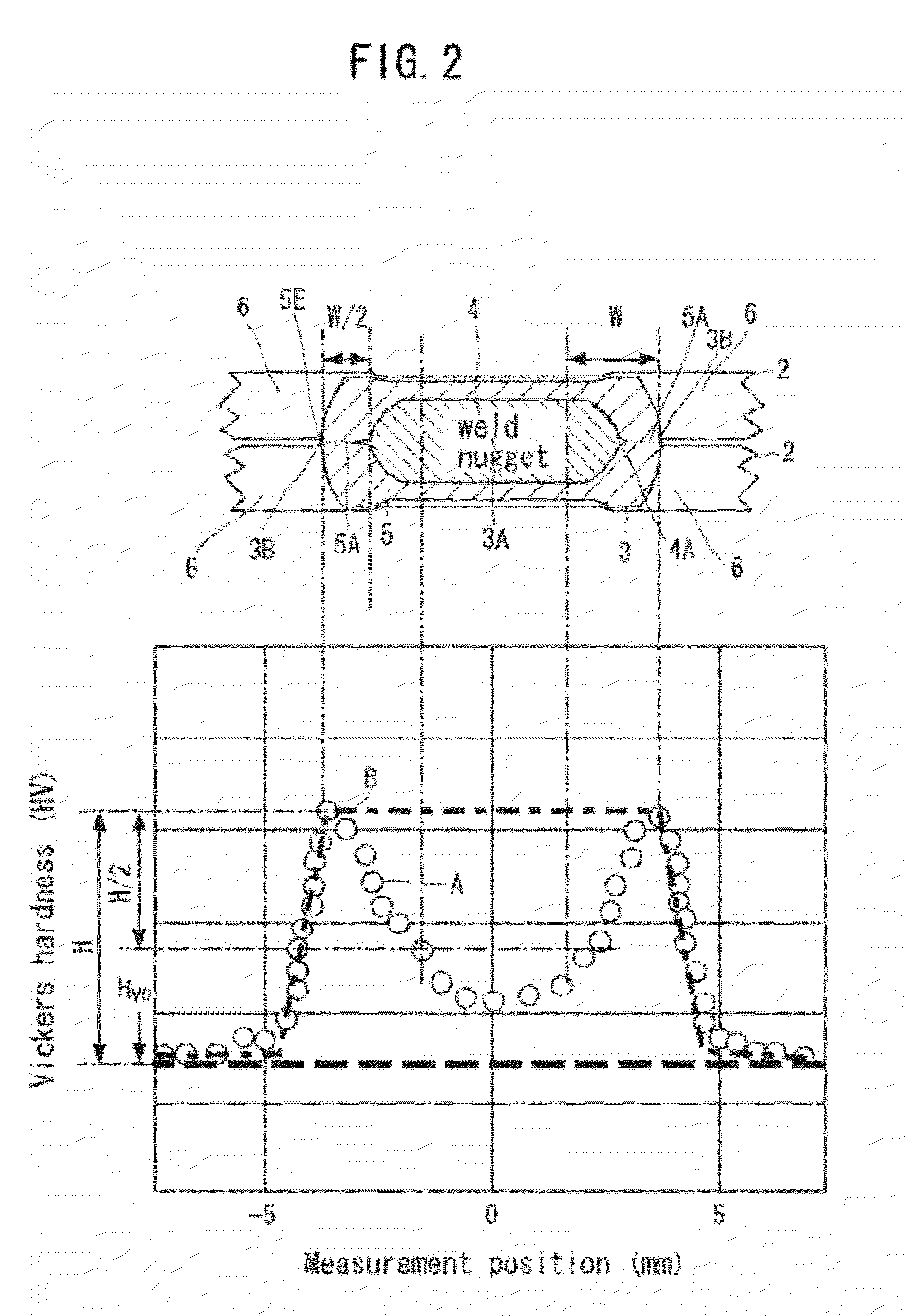
A welding structural part 1 is manufactured by overlapping the surfaces of steel sheets 2, and forming a weld zone by spot welding. The weld zone 3 includes: a weld nugget 4; and a heat affected zone 5 surrounding the weld nugget 4, wherein the hardness in the weld zone increases along an exterior region 6 of the heat affected zone 5 toward the heat affected zone 5, and then decreases along the heat affected zone 5 toward the central region of the weld nugget 4. In the boundary region between the weld nugget 4 and the heat affected zone 5, the weld nugget 4 may have a convex portion 4A bulging into the heat affected zone 5 along the overlapped portion. The steel sheets 2 contain carbon in 0.15 mass % or more.

Description

TECHNICAL FIELD [0001]The present invention relates to a welding structural part and a welding method of the same. More specifically, the present invention relates to a welding structural part including a highly ductile spot weld zone and a method of welding the structural part.BACKGROUND ART [0002]Spot welding equipment is used to weld steel sheets overlapped with each other. FIG. 21 is a cross-sectional view illustrating the conventional spot welding of steel sheets 50. As shown in FIG. 21, to perform spot welding of steel sheets 50, an overlapped portion of the steel sheets 50 is sandwiched between a pair of electrodes 52, and a force is applied to the electrodes 52 to pressurize the steel sheets 50 in the direction of the arrow as shown in FIG. 21. A large current on the order of kA is then applied to the electrodes 52 while the pressurized state is maintained to melt the compressed part instantaneously by Joule heating, namely by resistance heating, thus forming a melted mass o...

Claims


Application Information

Patent Timeline
Patent Type & Authority Applications(United States)
IPC IPC(8): B32B15/01B23K11/11
CPCB23K11/115B23K11/24B23K11/26Y10T428/12965B23K2201/18B23K2203/04C22C38/00B23K11/312B23K2101/006B23K2101/18B23K2103/04
Inventor KANAI, TAKAHIKOHATTA, MUNEHISAIKUTA, FUMIAKIKAWASAKI, KAZUHIRONAKANISHI, EIZABUROUMIYAKE, MASAYUKINAGAI, KOTOBUHAYAKAWA, MASAOITAGAKI, TAKEHIKO
Owner NETUREN CO LTD
Why Eureka
Try Eureka