Battery pack and manufacturing method thereof

Inactive Publication Date: 2012-05-24
PANASONIC CORP
View PDF2 Cites 15 Cited by
  • Summary
  • Abstract
  • Description
  • Claims
  • Application Information

AI Technical Summary

Benefits of technology

[0007]Thus, an object of this invention is to provide a battery pack a

Problems solved by technology

Thus, there is a problem in that it is difficult

Method used


Image

  • Battery pack and manufacturing method thereof
  • Battery pack and manufacturing method thereof
  • Battery pack and manufacturing method thereof

Examples


Example

[0018]Embodiments of the present invention are now explained with reference to the appended drawings. Note that the following embodiments are examples which embody the present invention, and are not intended to limit the technical scope of the present invention.

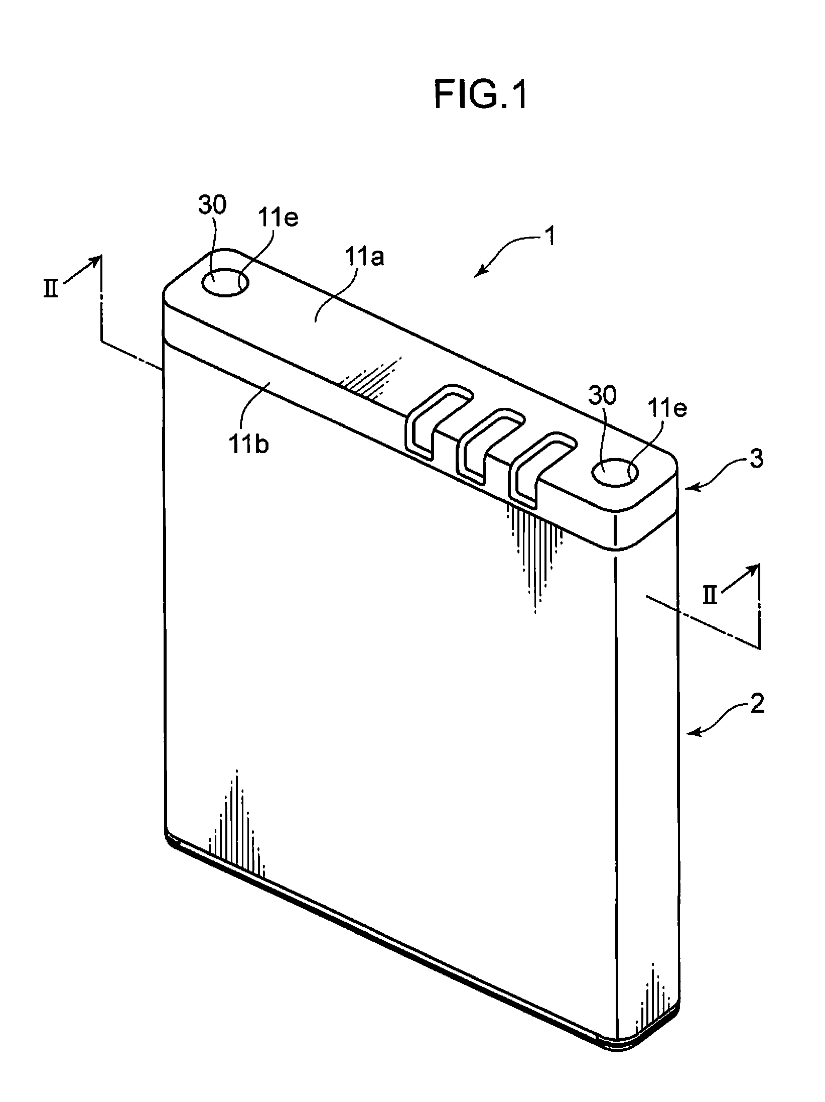
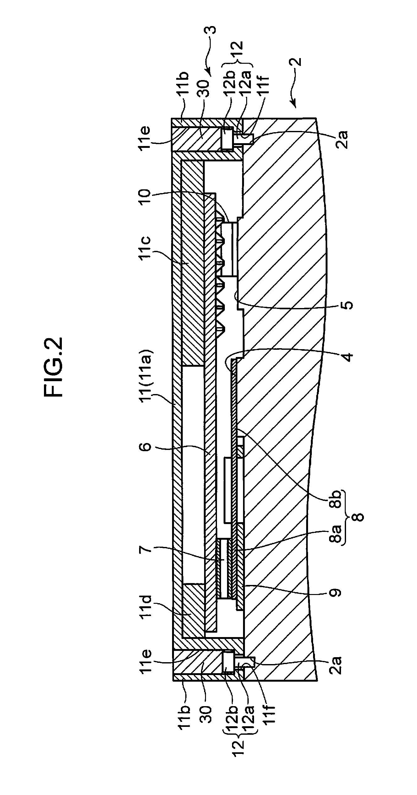
[0019]FIG. 1 is a perspective view showing the overall configuration of the battery pack according to an embodiment of the present invention. FIG. 2 is a cross section of line II-II of FIG. 1.

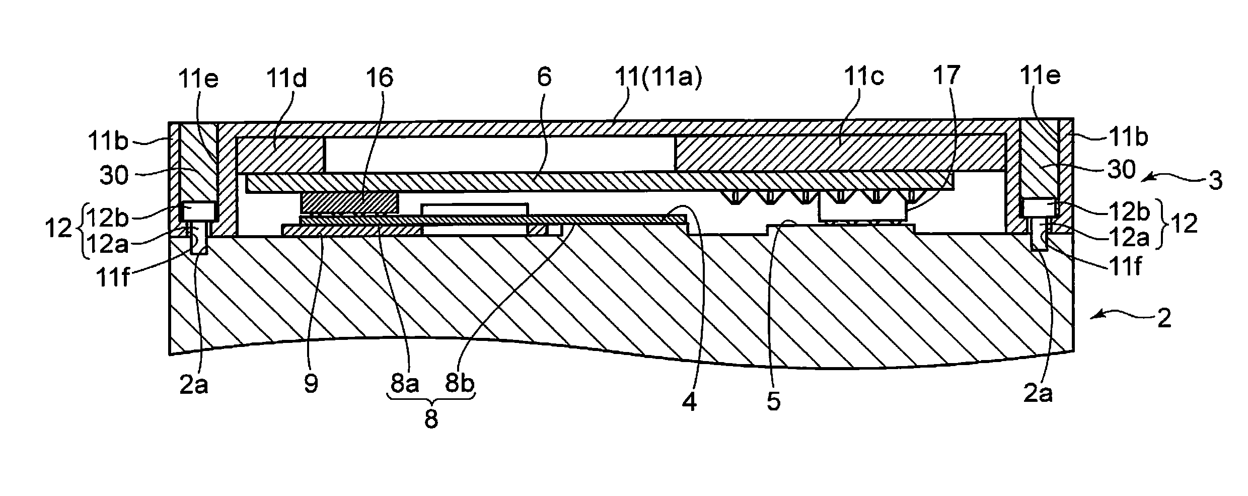
[0020]Referring to FIG. 1 and FIG. 2, a battery pack 1 comprises a laminar battery 2, and a safety member 3 fixed to an end face (upper face of FIG. 1) facing a direction (hereinafter referred to as the “vertical direction”) which is orthogonal to the thickness direction (hereinafter referred to as the “horizontal direction”) of the battery 2.

[0021]The battery 2 is a lithium ion battery. The battery 2 includes a negative electrode 4 and a positive electrode 5 formed on an end face facing upward. The negative electrode 4 and the positive ...


PUM

PropertyMeasurementUnit
Temperatureaaaaaaaaaa
Deformation enthalpyaaaaaaaaaa

Abstract

A battery pack and a manufacturing method thereof enabling the streamlining of assembly work are provided. This battery pack comprises a printed circuit board 6 including wiring, lead plates 7, 10 that are fixed to the printed circuit board 6 and that electrically connect the wiring of the printed circuit board 6 and both electrodes 4, 5 of a battery 2, and a screw 12 that presses the lead plates 7, 10 so as to maintain a state of electrically connecting of the lead plates 7, 10 to both electrodes 4, 5 of the battery 2 by being screwed into the battery 2.

Description

TECHNICAL FIELD[0001]The present invention relates to a battery pack mounted with a safety member for controlling a circuit so as to inhibit the occurrence of thermal runaway and internal short circuits when a cause of overcharge, overdischarge or the like is detected.BACKGROUND ART[0002]Generally speaking, a battery pack comprising a battery, and a safety member for inhibiting the occurrence of thermal runaway and internal short circuits of the battery is known. The safety member comprises a substrate, and a connecting member provided between the substrate and the battery and which is used for electrically connecting the substrate and the battery pole.[0003]For example, Patent Document 1 discloses a battery pack comprising a bare cell (battery), first and second electrode leads (connecting members) coupled to first and second electrode terminals (poles) of the bare cell, and a protective circuit board (substrate) which is electrically connected to the bare cell via the first and se...

Claims


Application Information

Patent Timeline
IPC IPC(8): H01M10/42H01M10/04H01M50/574
CPCH01M2/0215H01M2/0404H01M2/34Y10T29/49108H01M2200/00Y10T29/4911H01M10/4257Y02E60/10Y02P70/50H01M50/574H01M50/20H01M50/531
Inventor OTA, SHINJI
Owner PANASONIC CORP
Why Eureka
Try Eureka