Method and system for facilitating autonomous landing of aerial vehicles on a surface

Active Publication Date: 2012-05-24
SAAB AB
View PDF1 Cites 51 Cited by
  • Summary
  • Abstract
  • Description
  • Claims
  • Application Information

AI Technical Summary

Benefits of technology

[0011]By this is achieved a way of using image pattern analysis of a projected pattern instead of relying on information from time measurements of reflected laser beams. The use of image pattern analyzing means has an advantage over detecting the time difference between emitted and reflected laser beams since laser beams could be deflected. An image pattern may also be unaffected by obscurities and also clearly visible through e.g. fog or cloud in for example the infrared spectrum.

Problems solved by technology

A problem with the systems according to U.S. Pat. No. 4,995,722 and U.S. Pat. No. 4,868,567 are that they are dependent on devices placed on the landing platform, such as photosensitive cells or mirrors.

Method used


Image

  • Method and system for facilitating autonomous landing of aerial vehicles on a surface
  • Method and system for facilitating autonomous landing of aerial vehicles on a surface
  • Method and system for facilitating autonomous landing of aerial vehicles on a surface

Examples


Embodiment Construction

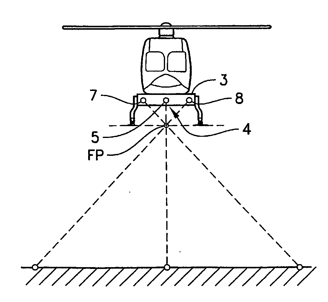
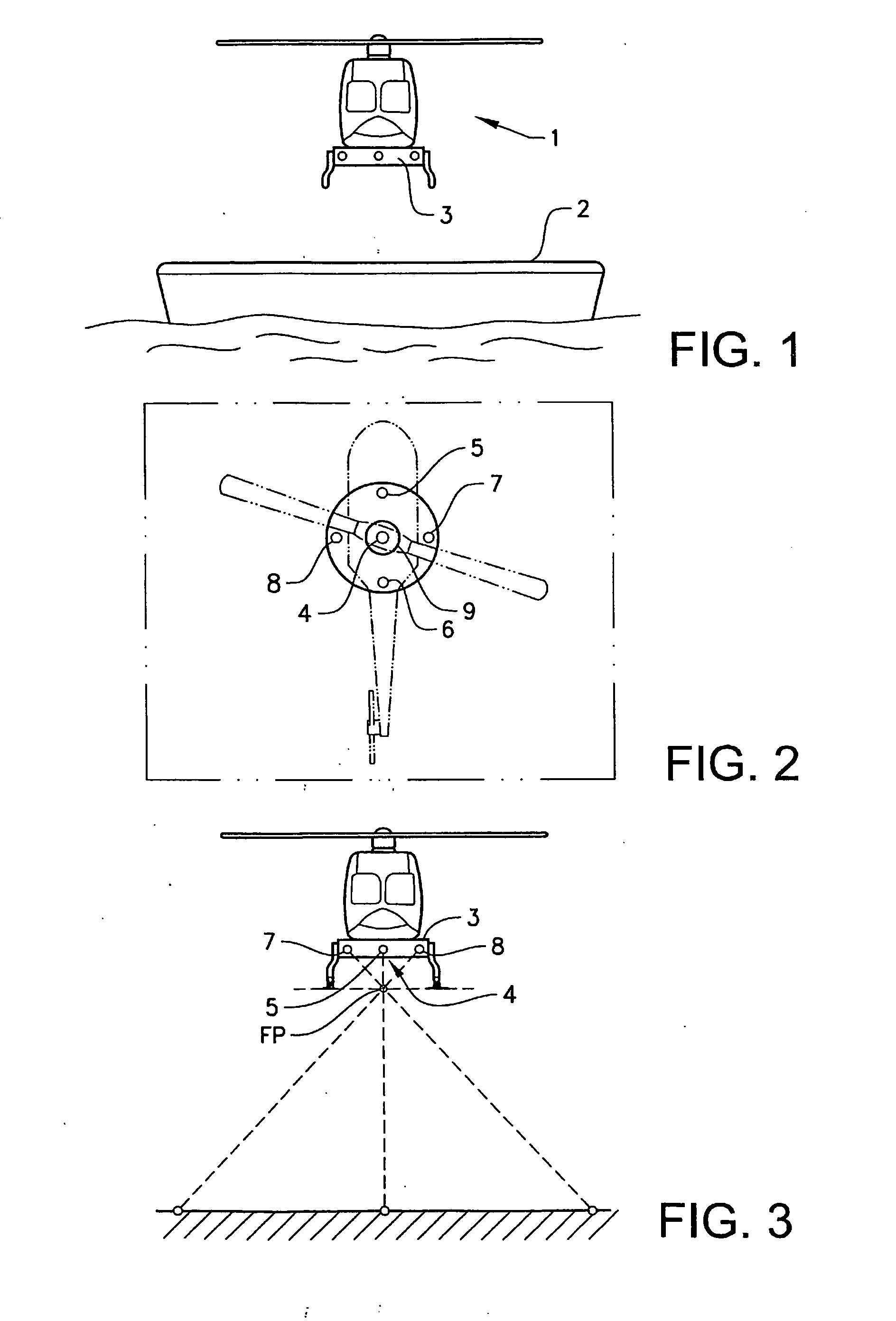
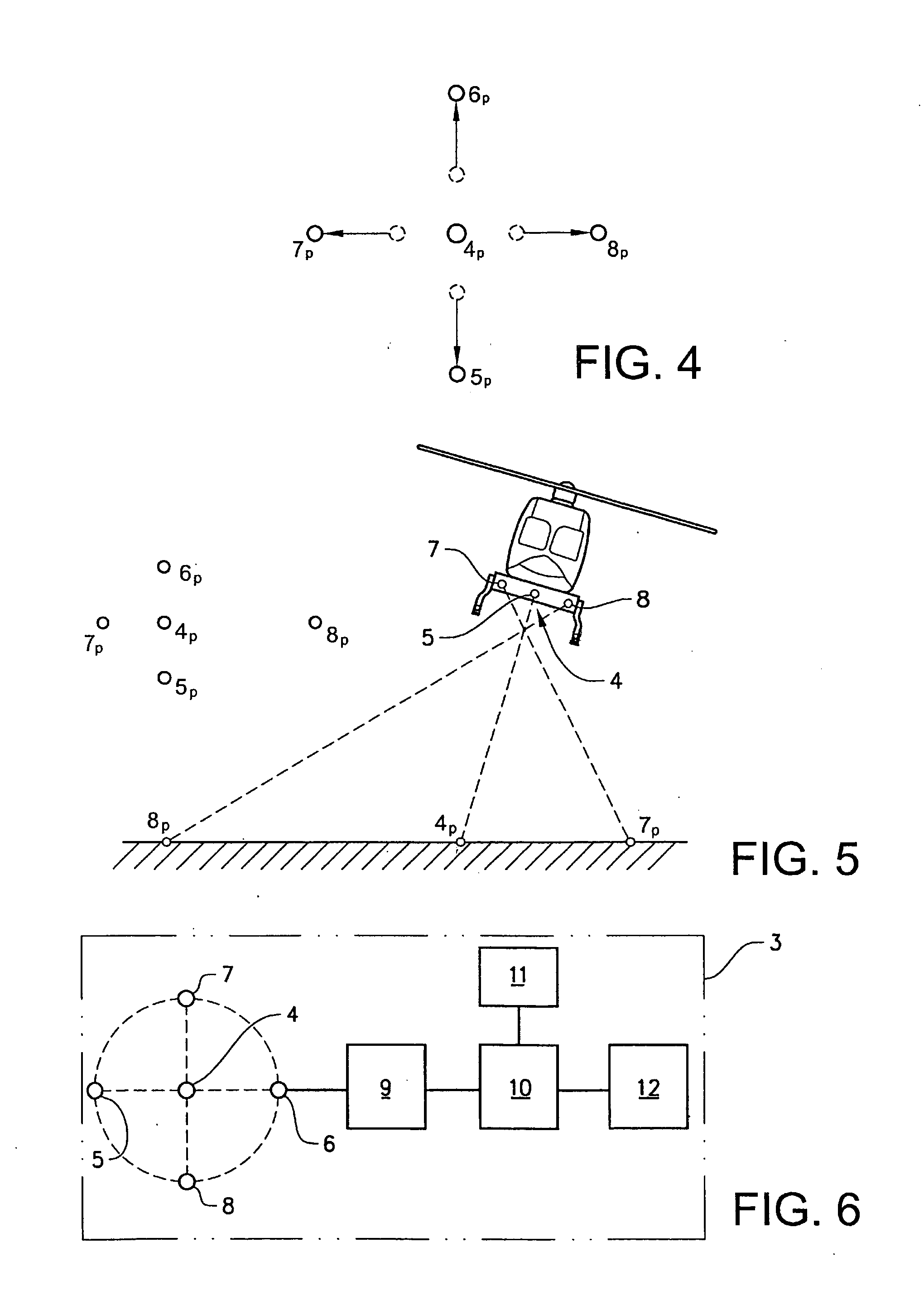
[0023]FIG. 1 shows an aerial vehicle 1, preferably an unmanned aerial vehicle (UAV), in the present case a helicopter, which has moved into a position above a surface 2 of a landing platform on a ship at sea. The UAV is equipped with a system 3 for autonomous landing. According to an embodiment of the invention FIG. 2 shows a helicopter seen from above and illustrates how the system 3, comprising five light sources 4,5,6,7,8 and a digital camera 9 is arranged beneath the helicopter. The five light sources 4,5,6,7,8 are arranged in a cross, where one light source 4 is positioned in the centre together with the digital camera 9, and from that light source the other four light sources 5,6,7,8 are positioned at equal distances in the same plane. Two of them 5, 6 are aligned with a longitudinal line which joins the front and back of the helicopter, and the other two light sources 7, 8 are aligned with a line perpendicular to that line in the same plane, i.e. a transverse line joining the...


PUM


Abstract

A system for facilitating autonomous landing of aerial vehicles on a surface. A beam emitter is directed downwards. A control module is configured to govern the vehicle. A processor processes image data. The beam emitter is arranged to emit simultaneously at least four beams directed towards the surface in order to project a pattern thereon. One beam emitter of the at least four beam emitters is placed in the center. An image capturing module captures subsequent images of the pattern.

Description

TECHNICAL FIELD[0001]The present invention relates to a system and a method for autonomous landing of aerial vehicles on a surface.BACKGROUND OF THE INVENTION[0002]When landing an aerial vehicle, such as an unmanned helicopter, it is important that the aerial vehicle has access to accurate information regarding movement, position and attitude relative to the surface of the landing area. In particular, when landing on the platform of a ship, the sea continuously effects the attitude of the ship and hence the landing platform. The movement of the platform has three degrees of freedom. The inclination is determined by the pitch and the roll, and there is also a movement in the vertical direction, for example if there is a heavy sea, the amplitude of the waves can change the distance between the ship and the vehicle by quite a large amount. It is therefore important to be able to determine when the helicopter is sufficiently parallel to the platform.[0003]U.S. Pat. No. 4,868,567 disclos...

Claims


Application Information

Patent Timeline
IPC IPC(8): G05D1/00
CPCG05D1/0684G05D1/0858
Inventor ANDERSON, DANIEL
Owner SAAB AB
Why Eureka
Try Eureka