Locking element

a technology of locking element and lock, which is applied in the field of locking element, can solve the problems of inability to adapt the lock spacing to containers of different sizes, and the container cannot be secured by the lock, and achieve the effects of lowering the lock, facilitating release, and reducing the shear force or torque acting on the fram

Active Publication Date: 2012-05-31
TELAIR INTERNATIONAL GMBH
View PDF16 Cites 4 Cited by
  • Summary
  • Abstract
  • Description
  • Claims
  • Application Information

AI Technical Summary

Benefits of technology

[0006]In some embodiments of the invention, at least one lock (preferably two) with claws for fixing the container can be moved and fixed in a guide of a frame of the locking element in the transverse direction of the aircraft (y; −y). Thus the position of the lock and hence the distance between locks to secure a container can be adapted to different container sizes. Preferably the lock has releasable fixing devices for fixing the lock to the guide in the frame so that the distance between locks of different locking elements can be modified easily and quickly.
[0014]In the locking element, load-holding devices can be provided such as rollers, ball rollers or follower rollers, wherein the load-holding devices are preferably arranged mobile in the frame. The load-holding devices facilitate movement of the container beyond the locking element in that they support a (part) load of the container and define the vertical position of the container relative to the lock. The mobility of the load-holding devices allows the load-holding devices to be arranged for example according to the position of the lock in the locking element. The load-holding devices can also be arranged removable so that if no load-holding devices are required, weight is saved.

Problems solved by technology

If the spacing of the locks does not correspond to the size of the container, the container cannot be secured by the locks.
Thus the lock spacing cannot be adapted to containers of different sizes.

Method used


Image

  • Locking element
  • Locking element
  • Locking element

Examples


Embodiment Construction

[0031]In the description below, the same reference numerals are used for the same parts and those with similar effect.

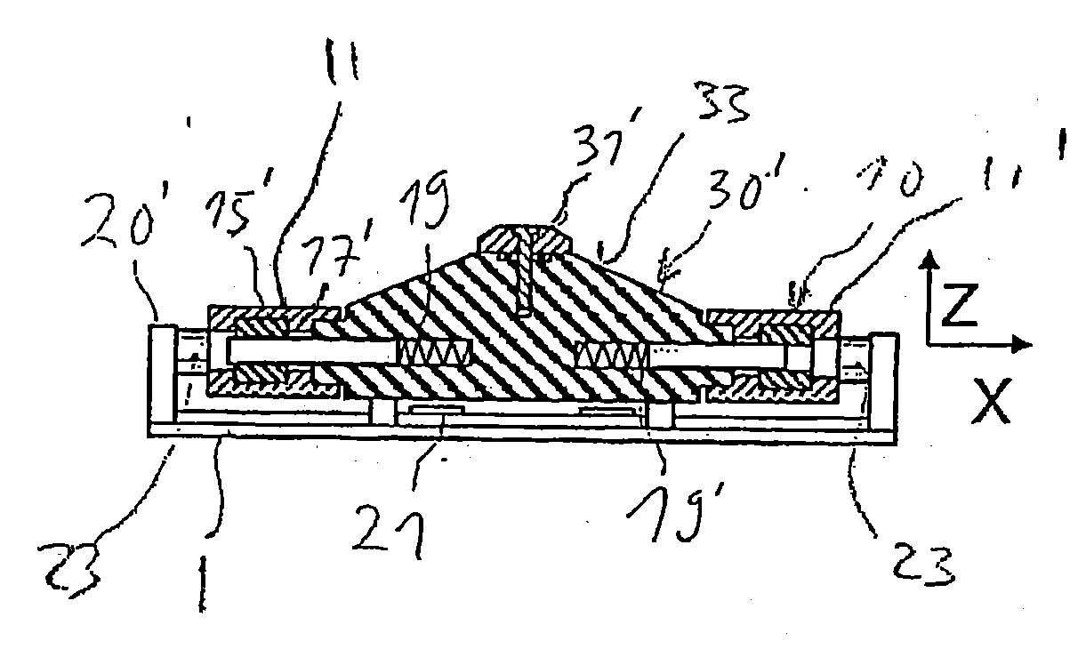
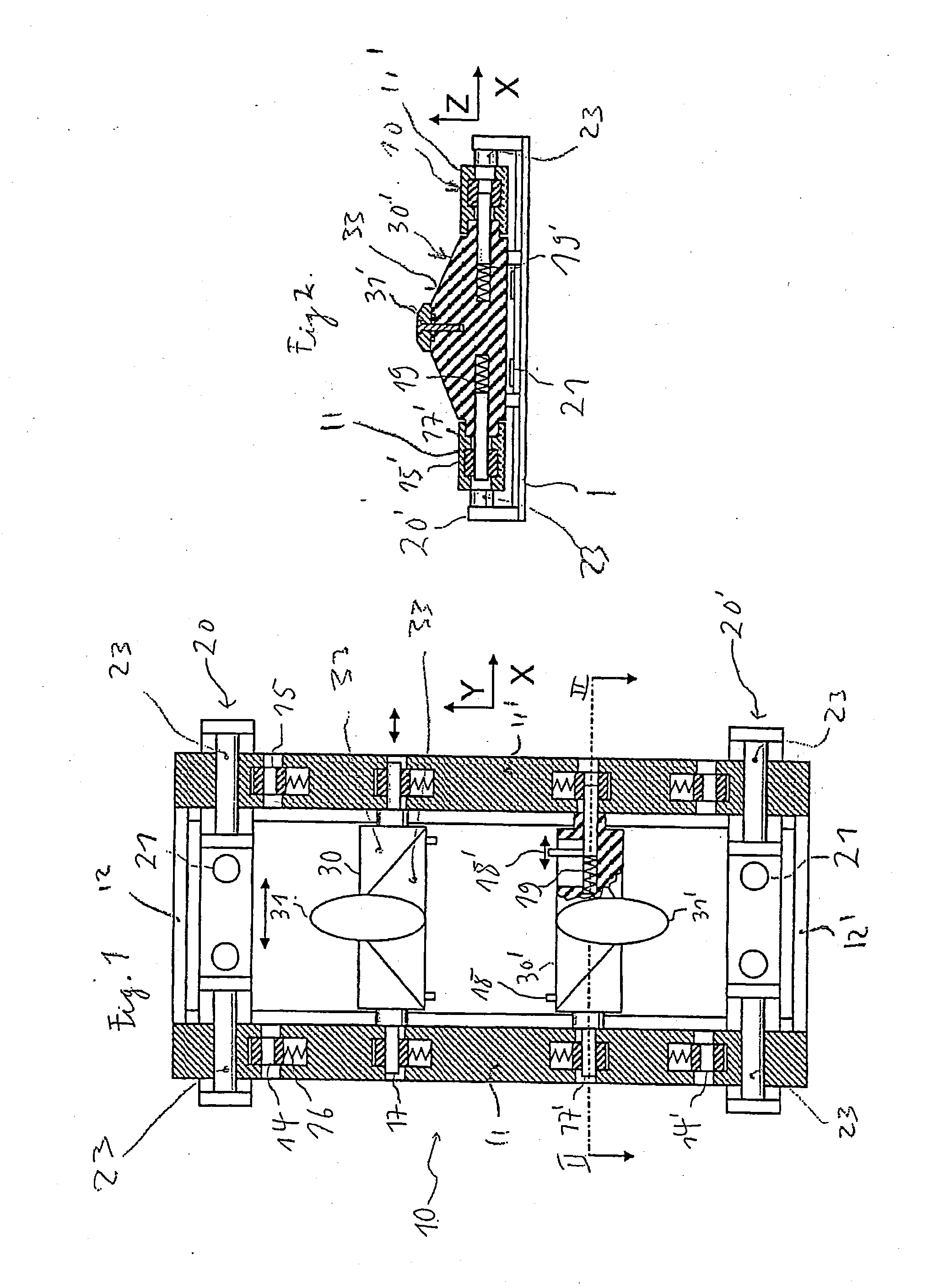
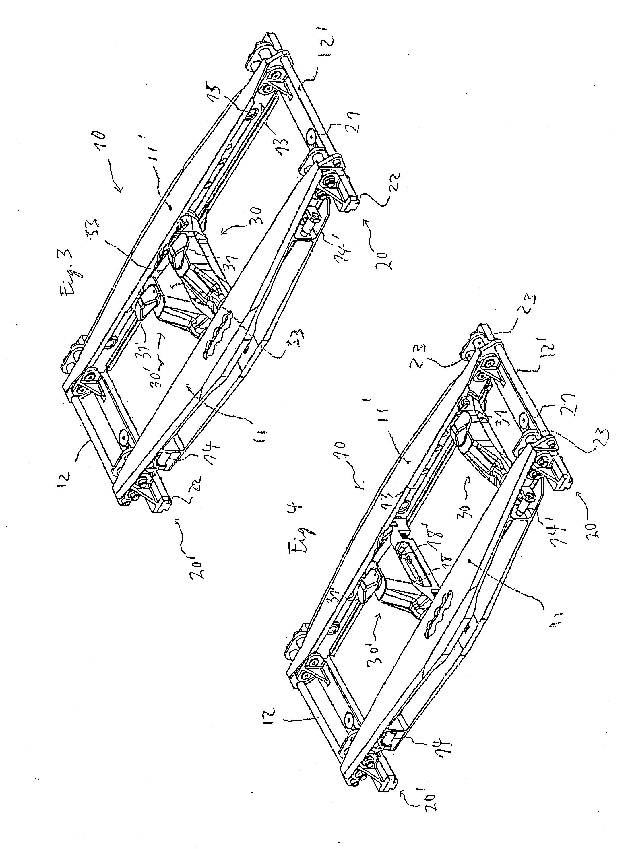
[0032]FIG. 1 shows a locking element in a diagrammatic view. The locking element comprises a frame 10 which has fixing devices 20, 20′ with which the frame 10 can be attached to a cargo bay floor 1 of an aircraft. The frame 10 comprises two side rails 11, 11′ with cross members 12, 12′ at the ends. On the frame 10 of the locking element are mounted two locks 30, 30′ mobile in the longitudinal direction of the locking element which corresponds to the transverse direction of the aircraft (y; -y), each of which comprises a claw 31, 31′. In a working position of the two locks 30, 30′, the claws 31, 31′ for holding the container (not shown) point in two opposing directions along the longitudinal direction of the locking element. The locks 30, 30′ are mobile in the longitudinal direction of the locking element in order to change quickly and easily the position of the locks...


PUM

PropertyMeasurementUnit
sizesaaaaaaaaaa
sizesaaaaaaaaaa
spring forceaaaaaaaaaa

Abstract

A lock is proposed for securing containers or similar freight on a cargo bay floor of an aircraft in a vertical direction perpendicular to the cargo bay floor and in a transverse direction perpendicular to a longitudinal direction of the aircraft. The locking element comprises at least one lock attached to a frame for securing containers or similar freight and with a claw in the transverse direction of the aircraft to surround and hold a part section of the container. At least one lock is arranged mobile and fixable in a guide of the frame in order to adapt the spacing of the locks to containers of different sizes.

Description

CROSS-REFERENCE TO RELATED APPLICATIONS[0001]This application claims priority to, and is a National Phase application of, pending PCT / EP2009 / 004484 entitled, LOCKING ELEMENT, filed Jun / . 22, 2009, the disclosure of which is hereby incorporated by reference in its entirety.FIELD OF THE INVENTION[0002]The invention concerns a locking element to secure containers or similar freight on a cargo bay floor of an aircraft, a cargo bay floor and the use of a locking element.BACKGROUND OF THE INVENTION[0003]Containers or similar freight to be secured on the cargo bay floor can be of different sizes. In particular there are various standard sizes for containers, e.g. 223.52 cm (88 inch) and 243.84 cm (96 inch). To secure the containers, locking elements with locks are used. The locks surround and hold a part section of the container. The distances between locks for holding containers must correspond to the size of the container concerned. If the spacing of the locks does not correspond to the ...

Claims


Application Information

Patent Timeline
Patent Type & Authority Applications(United States)
IPC IPC(8): B64C1/20B60P7/13B23P11/00B60P7/08
CPCB64D9/003Y10T29/49826Y02T50/46Y02T50/40
Inventor HUBER, THOMASHOLZNER, RICHARD
Owner TELAIR INTERNATIONAL GMBH
Why Eureka
Try Eureka