Eureka AIR delivers breakthrough ideas for toughest innovation challenges, trusted by R&D personnel around the world.

Charging cable plug for electric vehicles

Inactive Publication Date: 2012-05-31
INNOGY SE
View PDF25 Cites 38 Cited by
  • Summary
  • Abstract
  • Description
  • Claims
  • Application Information

AI Technical Summary

Benefits of technology

[0016]It is also possible for the identification data only to be present in encoded form in the charging cable plug, and loaded already in encoded form into the charging cable plug. At the transfer from the charging cable plug to the charging station, the identification signal transfers the encoded data, and there is no need for this data to be encoded in the charging cable plug itself. The decoding of the identification data, which is loaded into the charging station with the identification signal, can take place in the charging station. Accordingly, the public key for the loading station(s) would only have to be known at the programming of the charging cable plug. No logic system is then required in the charging cable plug itself in order to carry out the encoding. This reduces the costs of a charging cable plug. This is of advantage in particular if the identification data is semi-static. This data hardly changes, with the result that encoding in advance is possible.
[0017]According to an embodiment, it is also proposed that the housing has a receiver for a locking means of the charging column such that after the locking means has been received, the plug is secured by positive fit (form fit, form closure) to the charging column. For example, it is possible that after the locking means have been engaged in the charging cable plug, the charging cable plug is secured in the charging station such that it cannot be detached. The locking means for the charging station can be moved on receipt of the identification signal such that it can be moved into the receiver of the charging cable plug. This then prevents the charging cable plug from being pulled out of the charging station. This can prevent the possibility that after an activation of the supply of energy, the charging cable could be pulled unobserved out of the charging station, and the energy made available could be obtained by an unauthorised person.
[0018]Means may be provided which detect a forced separation of the charging cable from the charging station. Such detection means may be present in the charging station as well as in the charging cable plug. If these means detect a forced separation, the supply of energy can be stopped. This also prevents an unauthorised obtaining of the energy provided.

Problems solved by technology

It has also been recognised that user interfaces at the charging station, by means of which an identification could be made, are complicated to operate, and are rejected by users.
These solutions discourage users, however, from using the charging stations informally.

Method used


Image

  • Charging cable plug for electric vehicles
  • Charging cable plug for electric vehicles
  • Charging cable plug for electric vehicles

Examples


Embodiment Construction

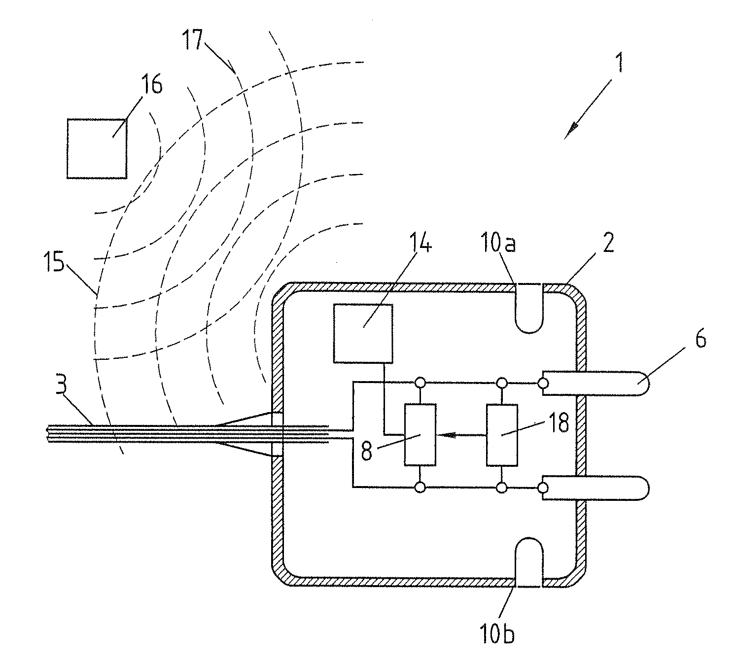
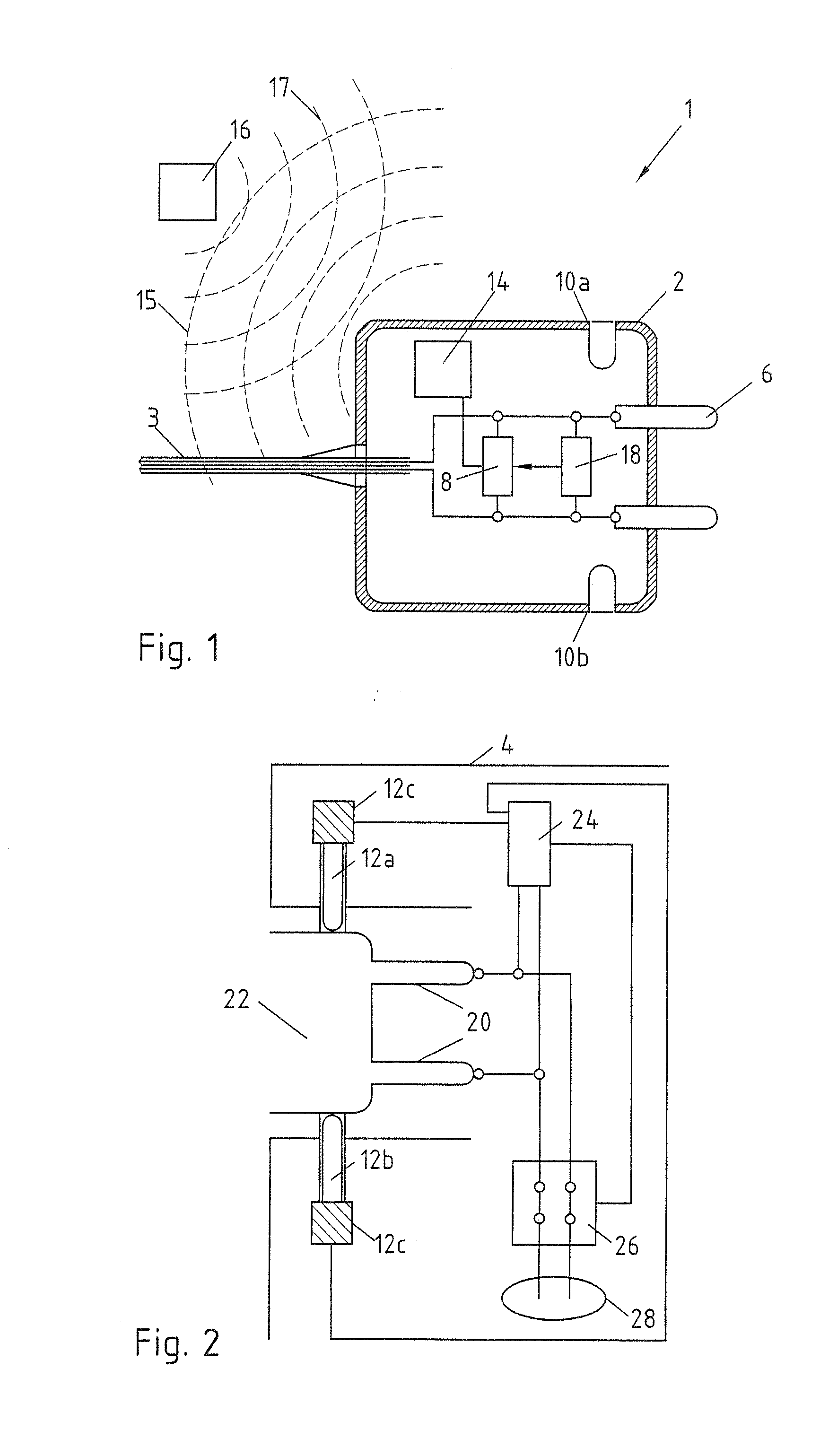
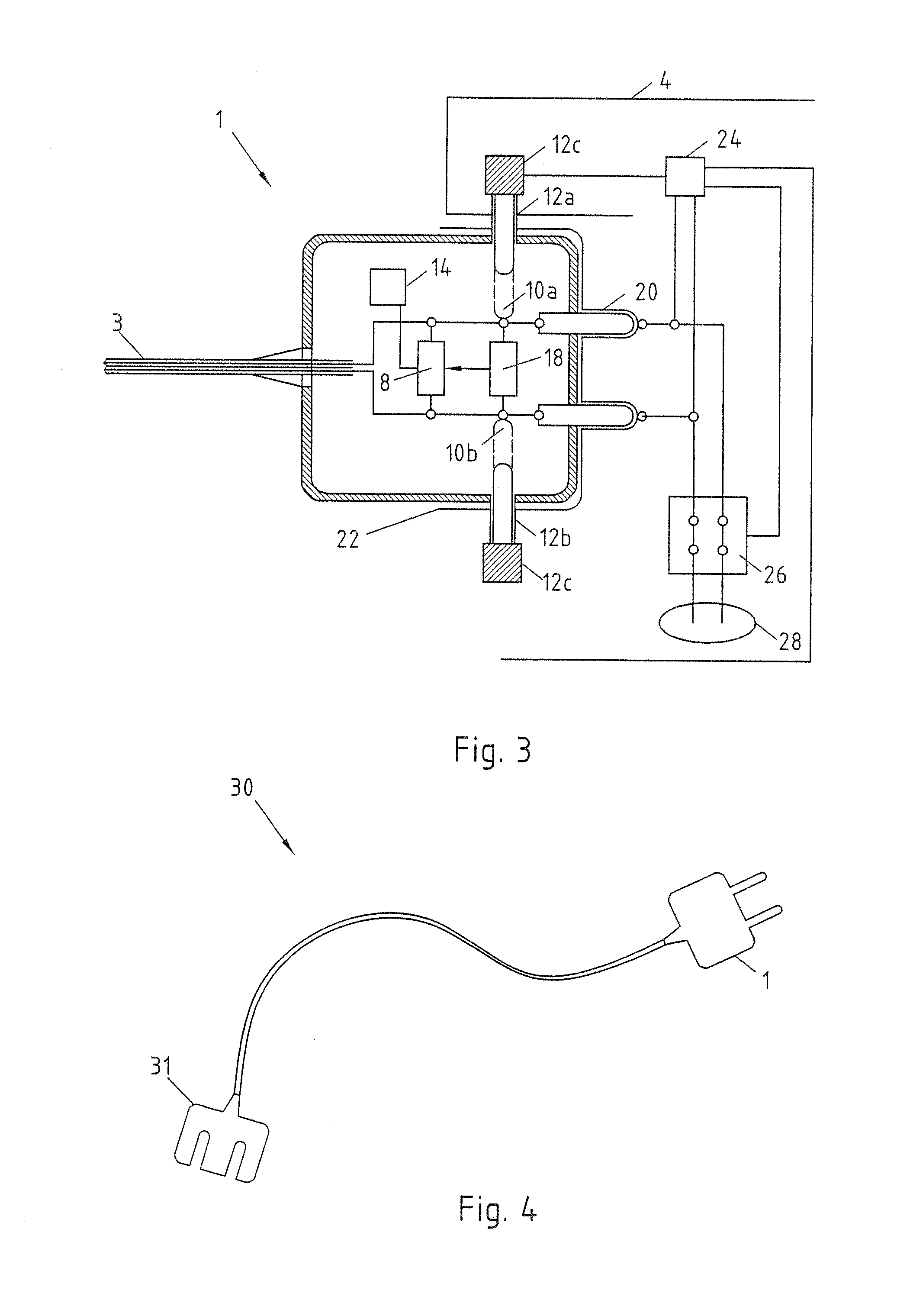
[0036]FIG. 1 shows a charging cable plug 1 with a housing 2. Leading into the housing 2 is a charging cable 3, which is connected to a socket on the side not shown, which can be connected to a vehicle. The housing 2 has electrical contacts 6. The electrical contacts 6 are electrically connected to the conductors of the charging cable 3. An electrical circuit is arranged in the housing 2 as identification means 8. This can be a microprocessor, on which the corresponding logic is stored. In addition, a reading means 14 is arranged in the housing 2. The reading means 14 is in operational connection with the identification means 8. The reading means 14 is a transponder reading device, which emits a reading field, such as a high-frequency 22 kHz signal 15, and can receive a transmitting field 17 of a transponder 16, for example likewise in the kHz range. Also provided in the housing 2 is a connection identification means 18, which can likewise be a microprocessor, on which the correspond...


PUM


Abstract

Charging cable plug 1 for electric vehicles, with a housing 2 and electrical contacts 6, arranged in the housing 2, for connection to a charging station 4. For simple identification before a charging procedure, an identification means 8 is proposed, arranged in the housing 2 and communicating with the charging station 4 via the electrical contacts 6.

Description

CROSS-REFERENCE TO RELATED PATENT APPLICATIONS[0001]This patent application is a continuation of International application No. PCT / EP2010 / 056518 filed on May 12, 2010, which claims the benefit of German application No. 10 2009 030 092.9 filed on Jun. 22, 2009, the teachings and disclosure of which are hereby incorporated in their entirety by reference thereto.FIELD OF THE INVENTION[0002]The subject-matter relates to a charging cable plug for electric vehicles with a housing and electrical contacts, arranged in the housing, for connection to a charging station. In addition to this, the subject matter relates to a charging cable with such a plug, as well as to a system with such a plug.BACKGROUND OF THE INVENTION[0003]The distribution of electrically powered vehicles will increase considerably in the near future. With the distribution of electric vehicles, however, new demands are being imposed on the supply infrastructure. Electric vehicles must be able to be supplied with electrical...

Claims


Application Information

Patent Timeline
IPC IPC(8): H01R3/00
CPCB60L11/1818H01R13/465B60L2270/32B60L2270/34H01R13/665Y02T90/121Y02T90/128Y02T90/14Y02T90/16Y02T90/163Y02T10/7088Y02T10/7005Y02T90/169Y04S30/14B60L11/1846Y02T10/7072B60L53/16B60L53/65Y02T90/12Y02T90/167Y02T10/70
Inventor GAUL, ARMINDIEFENBACH, INGO
Owner INNOGY SE
Why Eureka
Eureka Blog
Learn More