Room air purifier
a room air and purifier technology, applied in the field of air purification, can solve the problems of tens of billions of dollars in health care costs for the united states, lost productivity at work, and too many losses to cover here in detail
- Summary
- Abstract
- Description
- Claims
- Application Information
AI Technical Summary
Benefits of technology
Problems solved by technology
Method used
Image

Examples
first embodiment
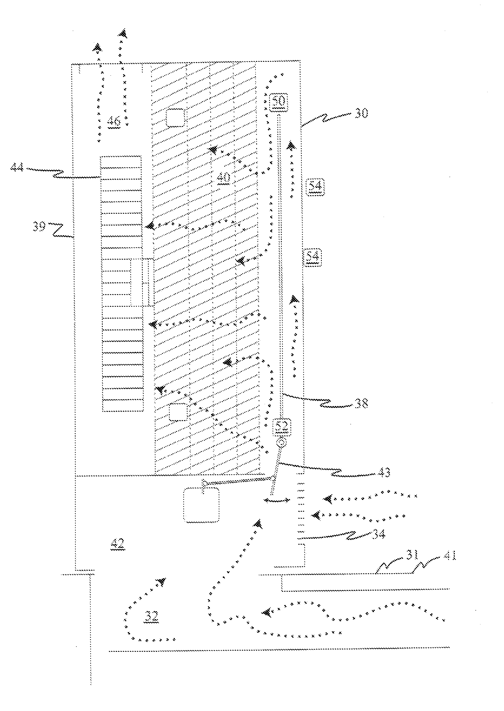
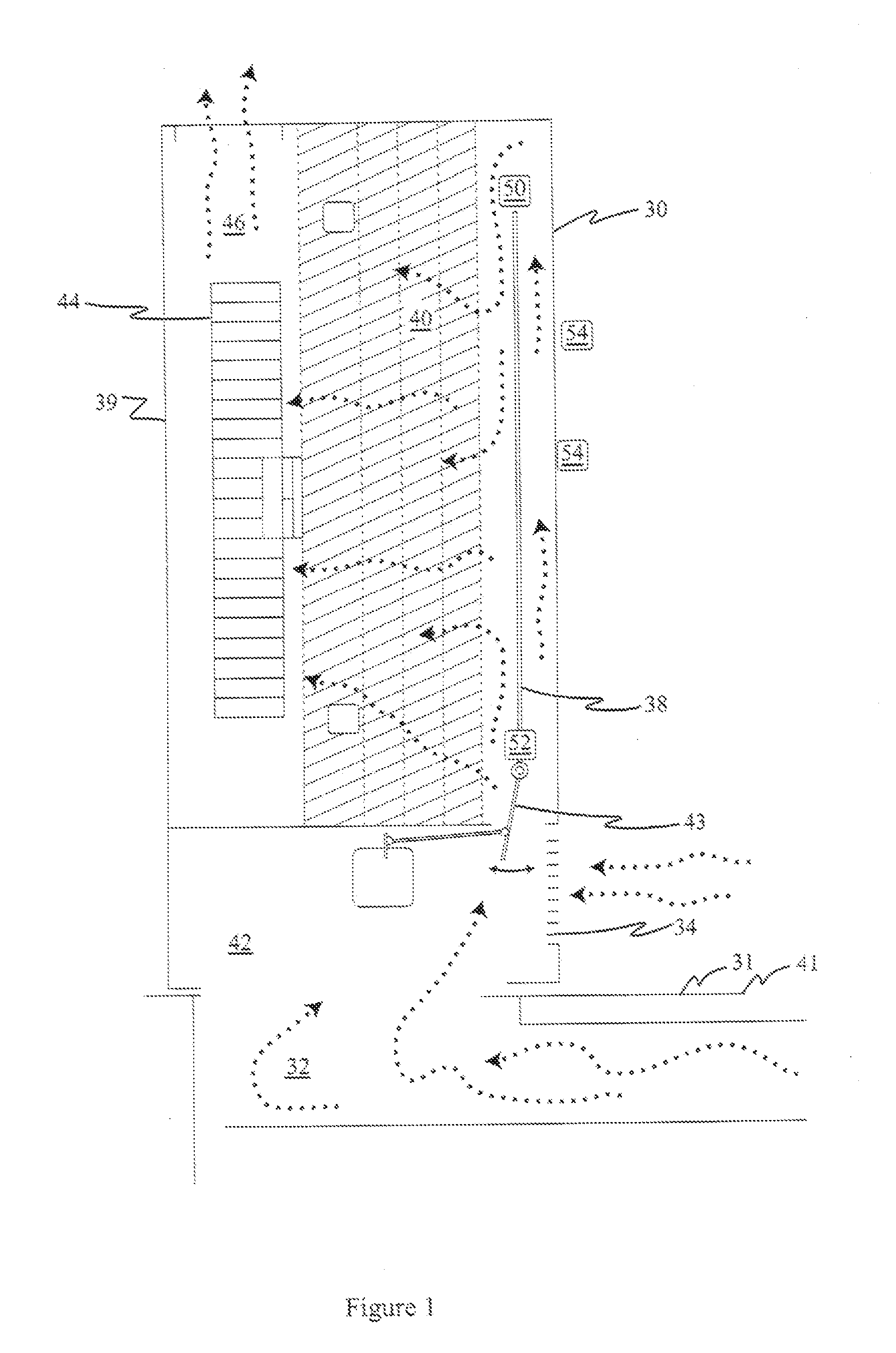
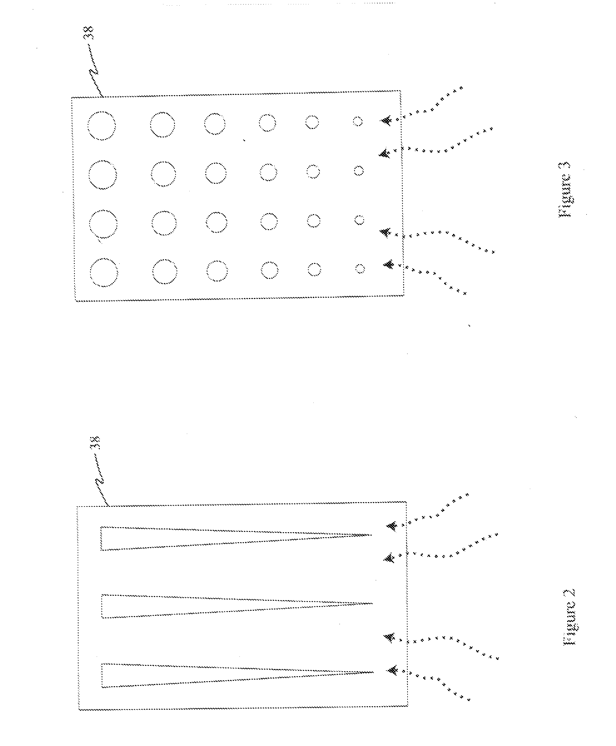
[0053]In FIG. 1, a room air purifier 30 of the present invention is shown. Room air purifier 30 is disposed on the floor 31 above floor supply duct 32. Room air purifier 30 is provided with a room air inlet 34. An air distribution panel 38 (alternatively referred to as an “air flow partition” in FIG. 24B) is spaced between one housing wall 39 and the inlet side of filter 40. Air distribution panel 38 can employ alternative structures. In one embodiment, air distribution panel is a solid panel. With a solid panel, it will be appreciated that air distribution panel 38 is spaced from the top of room air purifier 30 to allow air to flow around the top end of air distribution panel 38 for a “racetrack” air flow path (see also, FIG. 24B). In alternative embodiments, air distribution panel has a pattern of apertures, see FIG. 2 and FIG. 3, to modify the distribution of mass flow rate of air across the face of filter 40.
[0054]As shown in FIG. 1, filter 40 is preferably composed of multiple ...
third embodiment
[0073]Referring now to FIG. 9, a third room air purifier embodiment of the present invention is shown. In this embodiment, identical to FIG. 7, the room air purifier 30 has three inlets for drawing air, room air inlet 34, floor supply duct inlet 33, and wall supply duct inlet 66. In addition, the construction of the damper in FIG. 9, which controls and closes, air flowing through room air inlet 34 is identical to the construction in FIG. 7. The difference in the third embodiment is that the second damper 74 of FIG. 7, and associated mechanical elements such as a second damper motor 42A are omitted. Accordingly the embodiment shown in FIG. 9 is of simpler construction. It is recognized that there is now no ability to control the relative percentage of mass flow rate between the mass flow rate of air through floor supply duct inlet 33 and wall supply duct 66. It should be appreciated that in this embodiment, as in all other room air purifier embodiments described herein, that when a r...
fifth embodiment
[0076]Referring now to FIG. 11, which is a fifth room air purifier embodiment of the present invention, manually-adjusted louver 70 partially or fully restricts the mass flow rate of air entering room air purifier 30 through room air inlet 34. The first damper 72 shown in FIGS. 7 and 9 are also provided with this While already discussed above, position 1 of first damper 72 provides a crack opening so that air from chamber 35 may be drawn into room air purifier unit 30 to ensure positive pressure within the room, thus preventing outside unpurified air from entering the room. While not shown specifically in FIG. 11, an additional sail damper 56 (such as shown in FIG. 10) can also be added to manage two supply ducts 33, 66, preferentially to one another. It will also be appreciated that rather than a sail damper 56, the damper 74 shown in FIG. 7 could also be employed to manage the relative percentage of supply duct air flow through inlets 33 and 66 to provide temperature control, wit...
PUM
| Property | Measurement | Unit |
|---|---|---|
| Temperature | aaaaa | aaaaa |
| Flow rate | aaaaa | aaaaa |
| Width | aaaaa | aaaaa |
Abstract
Description
Claims
Application Information
 - R&D
- Intellectual Property
- Life Sciences
- Materials
- Tech Scout
- Unparalleled Data Quality
- Higher Quality Content
- 60% Fewer Hallucinations
Browse by: Latest US Patents, China's latest patents, Technical Efficacy Thesaurus, Application Domain, Technology Topic, Popular Technical Reports.
© 2025 PatSnap. All rights reserved.Legal|Privacy policy|Modern Slavery Act Transparency Statement|Sitemap|About US| Contact US: help@patsnap.com