High-performance shear friction damper

Active Publication Date: 2012-06-07
IND ACADEMIC COOP FOUND CHOSUN UNIV
View PDF6 Cites 33 Cited by
  • Summary
  • Abstract
  • Description
  • Claims
  • Application Information

AI Technical Summary

Benefits of technology

[0022]As described above, since the high performance shear friction damper can be easily installed to attenuate a vibration of a construction, and only friction plat

Problems solved by technology

In particular, the twisting generated in a building construction or a tower may cause severe shocks or collapse of the building construction or the tower.
However, the conventional dampers are costly and much higher costs are required in assembling the dampers with members of a building construction.
In addition, when friction plates mounted to offer a frictional force are abraded, the friction plates capable of attenuating a vibration may be functionally degraded and the entire damper structure is necessarily replaced, thereby resulting in increased maintenance and replacement costs
In addition, since the conventional damper, particularly, t

Method used


Image

  • High-performance shear friction damper
  • High-performance shear friction damper
  • High-performance shear friction damper

Examples


first embodiment

[0045]FIGS. 6 to 8 illustrate a high performance shear friction damper according to the present invention.

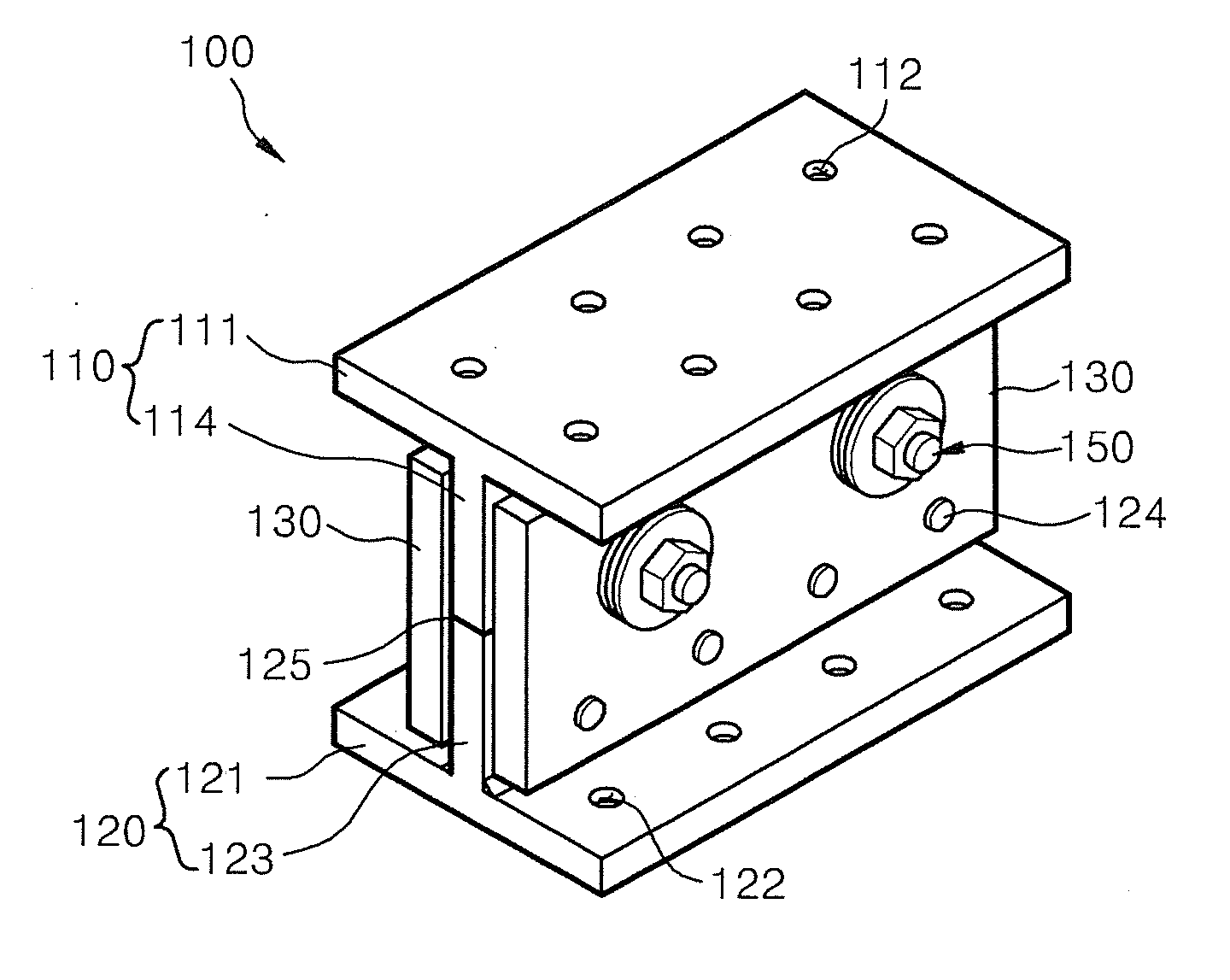
[0046]Referring to FIGS. 6 to 8, the high performance shear friction damper 100 includes first and second support bodies 110 and 120, prop plates 130 connecting first and second support bodies 110 and 120, friction plates 140 installed between the first support body 110 and the prop plates 130, and fastening units 150 for coupling the prop plates 130 to the friction plates 140.

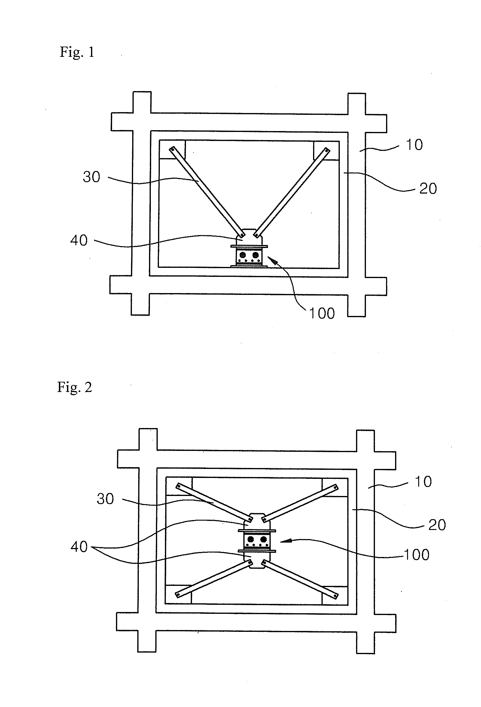
[0047]Referring back to FIG. 1, the first support body 110 includes a first end plate 111 fixed to a rod fastening member 40 connecting ends of the damping rods 30, and a sliding plate 114 downwardly extending from the first end plate 111.

[0048]A plurality of fastening holes 112 penetrating top and bottom surfaces of the first end plate 111 are formed in the first end plate 111, and achieve fastening using fastening members 60.

[0049]The sliding plate 114 downwardly extends a predetermined length from the b...

second embodiment

[0076]FIGS. 9 to 13 illustrate a high performance shear friction damper 200 according to the present invention.

[0077]The high performance shear friction damper 200 will be described with regard to an installed state shown in FIG. 1 with reference to FIGS. 9 to 13. The high performance shear friction damper 200 according to the second embodiment of the present invention includes first and second support bodies 210 and 220 supported to a rod fastening member 40 fastening a building construction 10 and damping rods 30, prop plates unit 240 coupled to front and rear surfaces of the first and second support bodies 210 and 220, first and second friction plates 231 and 233 inserted between the prop plate unit 240 and the first and second support bodies 210 and 220, and fastening units 250 fastening the first and second support bodies 210 and 220, the first and second friction plates 231 and 233 and the prop plate unit 240 to provide a predetermined level of friction durability.

[0078]The fi...

third embodiment

[0103]FIGS. 14 to 19 illustrate a high performance shear friction damper 300 according to the present invention.

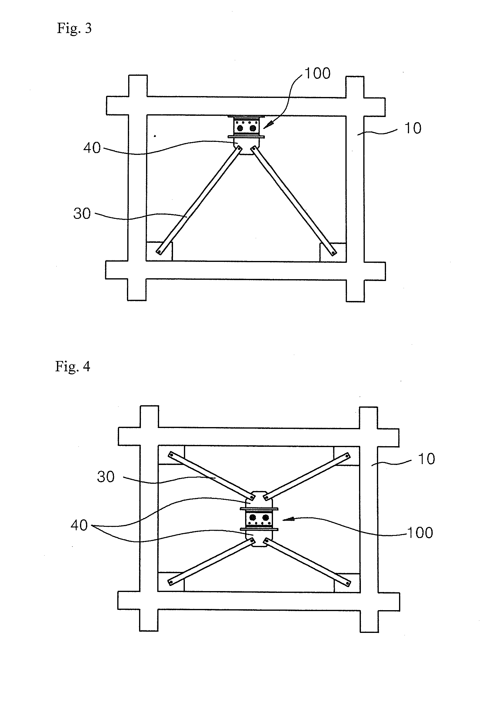
[0104]As shown in FIG. 14, a top end of the high performance shear friction damper 300 according to the third embodiment of the present invention is fixed to a building construction 10 and damping rods 30 are connected to both left and right sides thereof. Alternatively, the top end of the high performance shear friction damper 300 may also be installed to face downward.

[0105]In a case where an iron frame 20 for installing the damper 300 is provided, the top end of the high performance shear friction damper 300 may be coupled to the iron frame 20.

[0106]Referring to FIGS. 15 and 16, the high performance shear friction damper 300 includes an end plate 310 fixed to the building construction 10, a sliding panel unit 320 installed at a lower portion of the end plate 310, prop plates 360 installed on front and rear surfaces of the sliding panel unit 320, respectively, friction p...


PUM


Abstract

Disclosed is a high-performance shear friction damper provided in a building construction and attenuating a vibration which is applied to the building construction due to external loads such as an earthquake or strong wind. The high-performance shear friction damper includes first and second support bodies supported to a building construction or damping rods, two prop plates fixed to the second support body and extending to surround both side surfaces of the first support body, friction plates mounted between the first support body and the prop plates, and fastening units each including a tension bolt penetrating the first support body, the friction plates and the prop plates, and a nut fastened to an end of the tension bolt, wherein the first support body has slots extending in a horizontal direction, the tension bolts extend while penetrating the slots to allow the first support body to be slidably movable in the horizontal direction with respect to the friction plates.

Description

TECHNICAL FIELD[0001]The present invention relates to a high-performance shear friction damper, and more particularly, to a high-performance shear friction damper provided in a building construction and attenuating a vibration which is applied to the building construction due to external loads such as an earthquake or strong wind, and capable of effectively coping with external forces having various magnitudes.BACKGROUND ART[0002]When members of a building construction are subjected to horizontal external forces, the members are twisted or horizontally moved. In particular, the twisting generated in a building construction or a tower may cause severe shocks or collapse of the building construction or the tower.[0003]A damper plays an important role in protecting a building construction, for example, a house or the like, and exists in numerous modified forms.[0004]The damper attenuates movement by a frictional force between two movable parts fixed between members of a construction st...

Claims


Application Information

Patent Timeline
IPC IPC(8): E04B1/98F16F7/08E04H9/02
CPCE04H9/02F16F7/08E04H9/021E04H9/028E04H9/0235E04H9/0237
Inventor CHOI, JAE HYOUK
Owner IND ACADEMIC COOP FOUND CHOSUN UNIV
Why Eureka
Try Eureka