Rotor nozzle for a high-pressure cleaning appliance

a technology for cleaning appliances and rotor nozzles, which is applied in the direction of cleaning processes and apparatus, cleaning using liquids, and burners, etc. it can solve the problems of reducing the flow velocity of liquid in the area of at least one tangential inlet, reducing the reliability of the nozzle body, and reducing so as to improve the cleaning effect of the rotor nozzles and reduce the risk of turbulence. , the effect o

Active Publication Date: 2012-06-07
ALFRED KARCHER GMBH & CO KG
View PDF2 Cites 10 Cited by
  • Summary
  • Abstract
  • Description
  • Claims
  • Application Information

AI Technical Summary

Benefits of technology

[0029]The liquid supplied to the housing via the at least one tangential inlet can only leave the housing by flowing through the through-channel of the nozzle body and then passing through the depression, which has an opening, at the front wall of the housing. The through-channel expediently extends in the axial direction through the nozzle body. The liquid can, therefore, enter the through-channel at the rear end of the nozzle body and leave the through-channel at the front end of the nozzle body. It has been found that the cleaning effect of the rotor nozzle is improved by such a through-channel. The through-channel has a relatively large length. Turbulences in the flow of liquid are thereby calmed. Such turbulences can cause a fanning-out of the jet of liquid flowing out of the nozzle body. The risk of turbulences is reduced by the relatively large length of the through-channel.
[0030]It is particularly expedient for a flow straightener to be arranged in the through-channel as turbulences in the jet of liquid can thereby be calmed particularly effectively. The flow straightener may comprise walls which extend parallel to the longitudinal axis of the nozzle body and pass diametrically through the through-channel. In particular, it may be provided that the flow straightener comprises two walls extending perpendicularly to each other and parallel to the through-channel and passing diametrically through the through-channel.
[0031]A mass element which increases the centrifugal force and around which the liquid flows is expediently arranged in the rear end area of the through-channel. The mass element may be pressed into the through-channel. This facilitates assembly of the nozzle body.
[0032]It is particularly advantageous for a flow straightener which follows the mass element in the direction towards the front, spherical end of the nozzle body to be arranged in the through-channel. In such a configuration, the liquid can flow axially through the nozzle body, with it entering the through-channel at the rear end of the nozzle body and first flowing around the preferably spherical or cylindrical mass element. The liquid then flows through the flow straightener following the mass element in the direction towards the front end of the nozzle body. The flow straightener brings about a calming of the jet of liquid by turbulences in the jet of liquid being attenuated. A practically turbulence-free flow of liquid can be achieved, so that the risk of the jet of liquid fanning out as it leaves the nozzle body is particularly slight.

Problems solved by technology

The at least one tangential inlet does, however, form a flow resistance for the liquid, which results in flow losses.
However, this then has the consequence that the flow velocity of the liquid in the area of the at least one tangential inlet is reduced, and this, in turn, may have the consequence that the nozzle body cannot in all cases, be reliably caused to rotate about the longitudinal axis of the housing.
In particular, the so-called “start-up behavior” of the nozzle body may be impaired.
If the flow cross section of the at least one tangential inlet is now increased, in order to reduce flow losses in the area of the inlet, the flow velocity of the liquid in the area of the inlet is thereby reduced, and this may, in turn, have the consequence that the force exerted by the liquid on the nozzle body is not sufficient to cause the nozzle body to rotate about the longitudinal axis of the housing.

Method used


Image

  • Rotor nozzle for a high-pressure cleaning appliance
  • Rotor nozzle for a high-pressure cleaning appliance
  • Rotor nozzle for a high-pressure cleaning appliance

Examples


Embodiment Construction

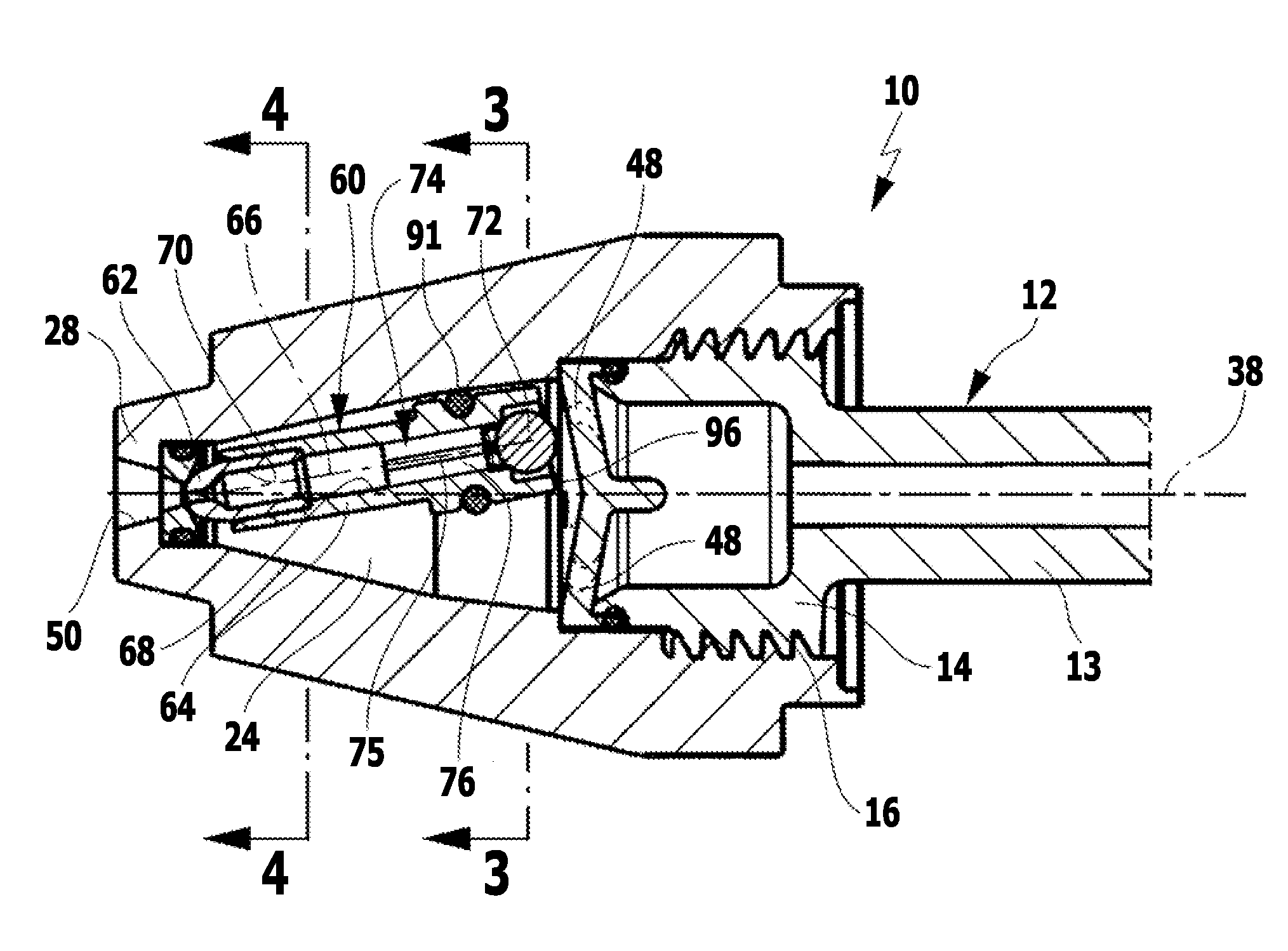
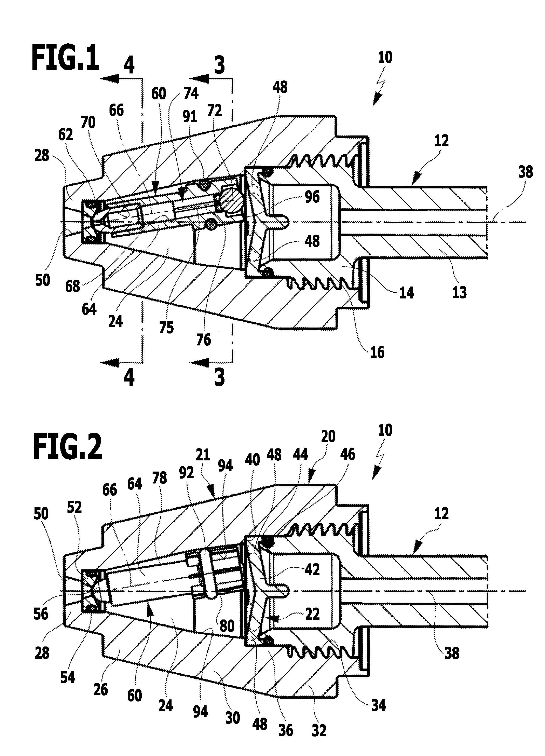
[0038]A rotor nozzle 10 for a high-pressure cleaning appliance, not represented in the drawings, is shown diagrammatically in the drawings. The rotor nozzle 10 is screwed onto a jet pipe 12 of the high-pressure cleaning appliance. The jet pipe 12 is only partially reproduced in the drawings as it is known per se to the person skilled in the art. It comprises a pipe section 13, at whose end, not shown in the drawings, facing away from the rotor nozzle 10, the pressure hose of the high-pressure cleaning appliance can be connected in the usual manner, and also a connecting section 14 with an external thread 16 for releasable connection of the jet pipe 12 to the rotor nozzle 10.

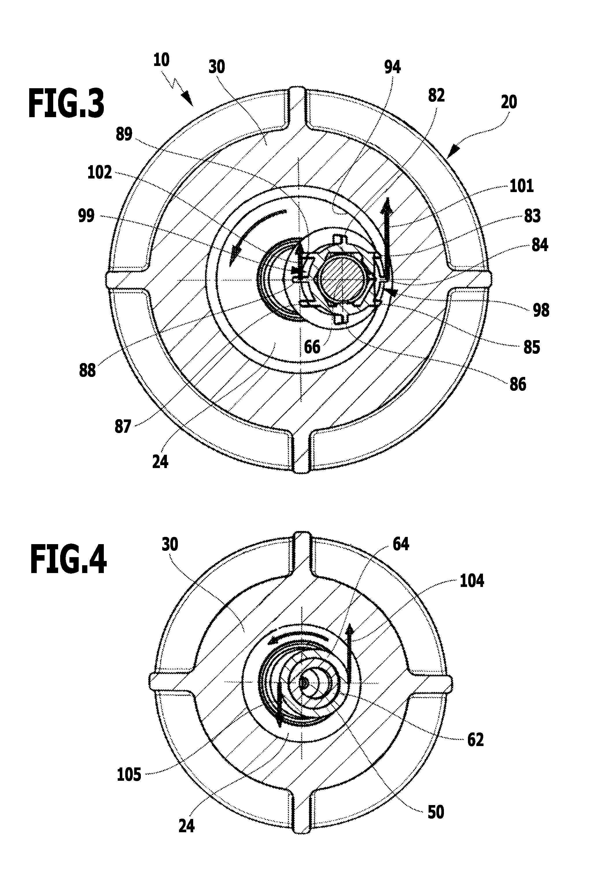
[0039]The rotor nozzle 10 comprises a housing 20 with a first housing part 21 and a second housing part 22, which define an interior 24. The first housing part 21 has a frustoconical front housing section 26 with a front wall 28 and a casing 30, and a rear housing section 32, which integrally adjoins the front ho...


PUM


Abstract

A rotor nozzle for a high-pressure cleaning appliance is provided. The rotor nozzle has a housing, which comprises at least one inlet opening tangentially, and which is provided in a front wall with a pan-shaped depression with a central opening. A nozzle body is arranged in the housing and supported with a spherical end in the pan-shaped depression. A longitudinal axis of the nozzle body is inclined to the longitudinal axis of the housing, it being possible for liquid in the housing to be caused to rotate about the longitudinal axis, and the nozzle body rotating together with the rotating liquid. In order to reduce flow losses in the rotor nozzle, without the operation of the rotor nozzle (in particular, start-up behavior of the nozzle body) being noticeably impaired, the nozzle body is provided with an outer contour deviating from the circular shape in a rear end area.

Description

[0001]This application is a continuation of international application number PCT / EP2010 / 057080 filed on May 21, 2010 and claims the benefit of German application number 10 2009 023 647.3 filed on May 25, 2009.[0002]The present disclosure relates to the subject matter disclosed in international application number PCT / EP2010 / 057080 of May 21, 2010 and German application number 10 2009 023 647.3 of May 25, 2009, which are incorporated herein by reference in their entirety and for all purposes.BACKGROUND OF THE INVENTION[0003]The invention relates to a rotor nozzle for a high-pressure cleaning appliance with a housing, which comprises at least one inlet for a liquid opening tangentially into the housing, and which is provided in a front wall with a pan-shaped depression with a central opening, and with a nozzle body arranged in the housing, the nozzle body having a through-channel and being supported with a spherical end in the pan-shaped depression, and the longitudinal axis of the noz...

Claims


Application Information

Patent Timeline
Patent Type & Authority Applications(United States)
IPC IPC(8): B05B3/02
CPCB08B3/02B05B3/0463
Inventor WESCH, JOHANN GEORGTRAUTWEIN, KAI
Owner ALFRED KARCHER GMBH & CO KG
Why Eureka
Try Eureka