Thrust reversal device

a technology of thrust reversal and reversing gear, which is applied in the direction of machines/engines, spraying apparatuses, jet propulsion plants, etc., can solve the problems of noisy performance, difficult maintenance operations, and complicated motor management, and achieve the effect of reducing or even cancelling the aerodynamic disruption and power loss

Inactive Publication Date: 2012-06-07
AIRCELLE
View PDF6 Cites 25 Cited by
  • Summary
  • Abstract
  • Description
  • Claims
  • Application Information

AI Technical Summary

Benefits of technology

[0034]According to one alternative embodiment, the device comprises a braking system of the lead screw in the guide means. Such a system in particular allows precise control of the deployment kinematics of the flaps. In fact, when the brake guide is engaged, the lead screw is blocked in rotation. As a result, the mobile cowl and the lead screw translate, but the guide means does not convert the translational movement into a rotational movement. The flaps are therefore not actuated. Monitoring and control electronics can

Problems solved by technology

Such a configuration of the prior art has several problems, in particular problems of different opening kinetics between the translation of the cowling and the pivoting of the flaps, aerodynamic problems due to the guide connecting rods passing through the tunnel, acoustic performance problems due to the installation of stationary articulation points that reduce the surface of the inner structure that can be used for acoustic treatment, and mechanical problems due to the mechanical connection using the connecting rods between the thrust reverser and the inner structure.
In fact, during a transition phase between the openi

Method used


Image

  • Thrust reversal device
  • Thrust reversal device
  • Thrust reversal device

Examples


Embodiment Construction

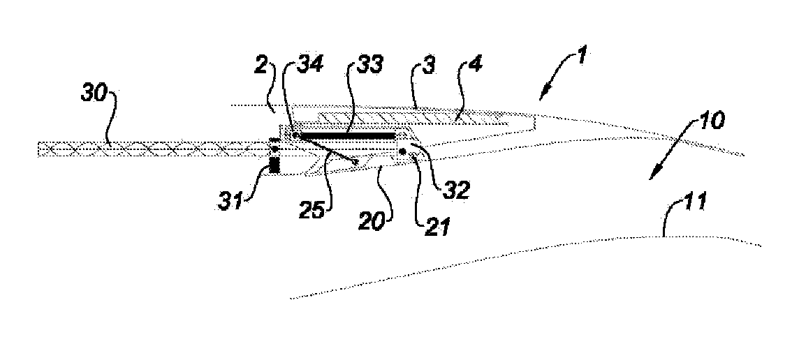
[0051]In a known manner, the thrust reverser 1 shown in FIG. 1 is associated with a dual-flow turbojet engine (not shown) and belongs to an external nacelle that defines, with a concentric inner structure 11, an annular flow channel 10 (also called tunnel) of a secondary flow of the turbojet engine.

[0052]The thrust reversal device comprises a stationary front frame 2 extended by a cowl 3 slidably longitudinally mounted.

[0053]More specifically, it will be noted that a thrust reversal device generally comprises at least two substantially semi-cylindrical mobile cowls 3 mounted on the nacelle so as to be able to slide along guideways (not shown).

[0054]The front frame 2 supports a plurality of cascade vanes 4 housed in the thickness of the mobile cowl 3 when the latter is in the closed position.

[0055]The translation of the mobile cowl 3 in the downstream direction of the nacelle releases an opening in the latter through which the secondary flow of the turbojet engine can at least partia...


PUM


Abstract

The present invention relates to a thrust reversal device (1) for a turbojet engine nacelle, characterized in that: (i) the movable cowl (3) is provided with at least one driving lead screw (30) having at least one peripheral groove over at least part of the length thereof, whereby said groove can engage with a stationary guide means (31) of the nacelle so as to rotate the lead screw during the translational movement of the movable cowl; and (ii) the lead screw is associated with at least one means for transmitting (32, 35, 36) the rotational movement thereof towards at least one drive system (33, 34, 25) of the flap.

Description

TECHNICAL FIELD[0001]The invention relates to a thrust reverser, called a grid reverser or a cascade reverser, for a jet engine.BRIEF DISCUSSION OF RELATED ART[0002]An airplane is moved by several turbojet engines each housed in a nacelle also housing a set of related actuating devices relative to its operation and performing various functions when the turbojet engine is running or stopped. These related actuating devices in particular comprise the mechanical thrust reversal system.[0003]A nacelle generally has a tubular structure comprising an air intake upstream of the turbojet engine, a middle section intended to surround a fan of the turbojet engine, a downstream section housing the thrust reversal means and intended to surround the combustion chamber of the turbojet engine, and generally ends with a jet nozzle whereof the outlet is situated downstream of the turbojet engine.[0004]Modern nacelles are intended to house a dual-flow turbojet engine capable of generating, via the ro...

Claims


Application Information

Patent Timeline
IPC IPC(8): F02K1/56
CPCF02K1/763F02K1/72
Inventor VAUCHEL, GUY BERNARD
Owner AIRCELLE
Why Eureka
Try Eureka