Method for Controlling a Voltage Transformer for Overvoltage Protection, Voltage Transformer and Operating Device having a Voltage Transformer

a voltage transformer and overvoltage protection technology, applied in the direction of efficient power electronics conversion, emergency protective circuit arrangement, electric lighting sources, etc., can solve the problem of simple and virtually costless measurement possibility

Inactive Publication Date: 2012-06-07
OSRAM GMBH
View PDF2 Cites 39 Cited by
  • Summary
  • Abstract
  • Description
  • Claims
  • Application Information

AI Technical Summary

Benefits of technology

[0004]It is an object of the invention to provide a method for controlling a voltage transformer for operating a switchable load, with at least one inductance and a switch which is controlled by means of a digital control device, in which the detection of an excessive input voltage works better. It is likewise an object of the invention to provide a voltage transformer and an operating device with such a voltage transformer that perform the aforementioned method.SUMMARY OF THE INVENTION
[0006]In this case, when the output voltage goes below a predetermined voltage limit of the non-operating voltage transformer, the load can also be reconnected. This gives rise to a reversible fault, in the case of which the entire arrangement resumes normal operation when the fault disappears. As a result, the service life can be extended, and operating convenience increases.
[0007]The switchable load preferably has an inverter and a gas discharge lamp, wherein the switchable load is disconnected by the operation of the inverter being suspended. Consequently, the entire arrangement corresponds to an electronic operating device for gas discharge lamps that has improved overvoltage protection in comparison with the prior art.

Problems solved by technology

In the case of digital controls, this provides a simple and virtually costless possibility for measurement, since the switch-off time of the switch when operating at the ripple limit is, as a matter of principle, known to the digital control.
This gives rise to a reversible fault, in the case of which the entire arrangement resumes normal operation when the fault disappears.

Method used


Image

  • Method for Controlling a Voltage Transformer for Overvoltage Protection, Voltage Transformer and Operating Device having a Voltage Transformer
  • Method for Controlling a Voltage Transformer for Overvoltage Protection, Voltage Transformer and Operating Device having a Voltage Transformer
  • Method for Controlling a Voltage Transformer for Overvoltage Protection, Voltage Transformer and Operating Device having a Voltage Transformer

Examples


Embodiment Construction

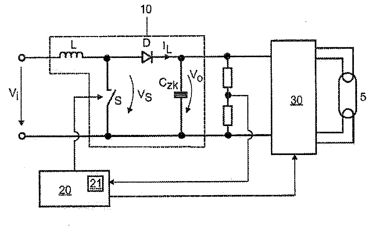
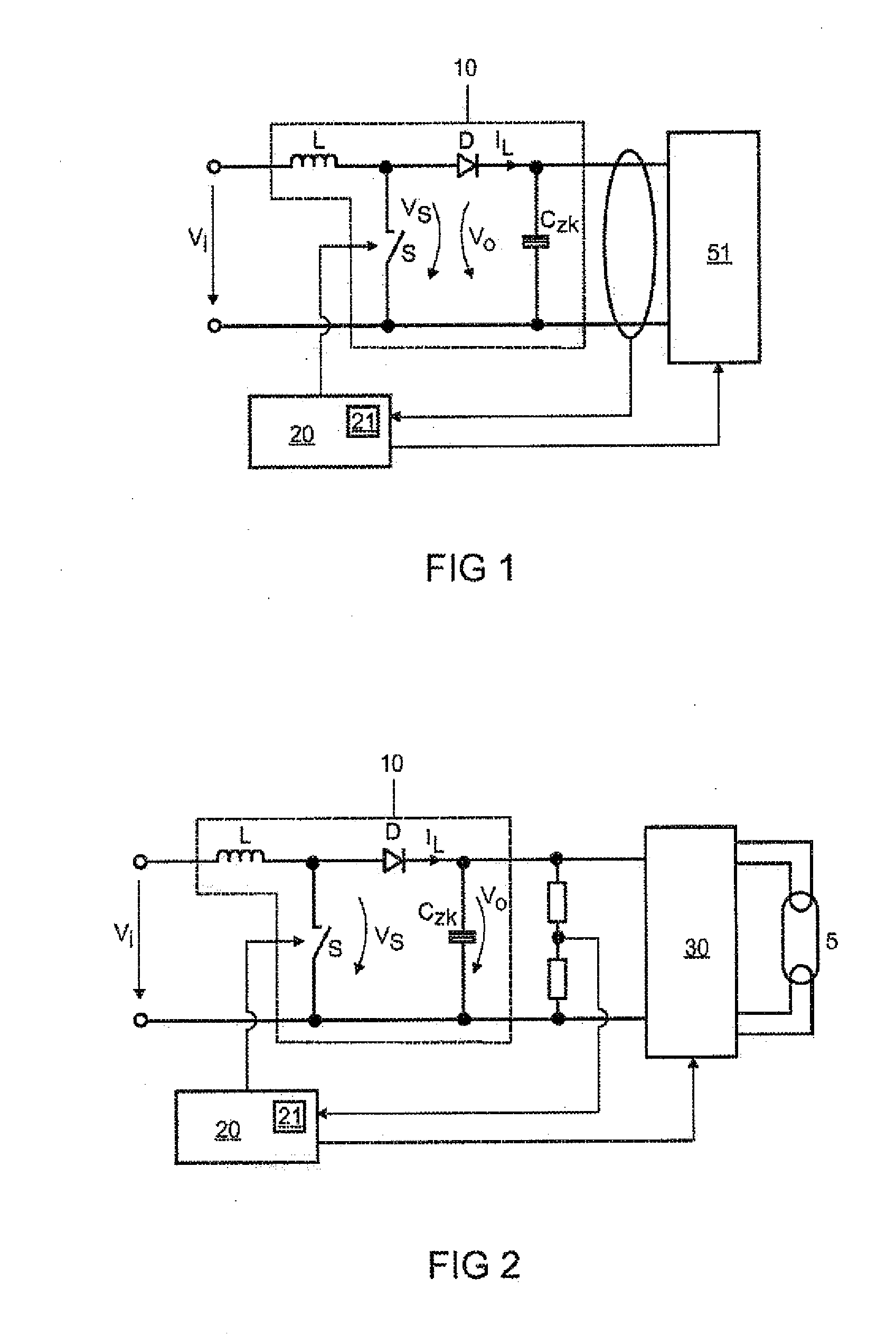
[0019]FIG. 1 shows the schematic representation of the voltage transformer 10, which supplies energy to a switchable load and performs the method according to the invention. The voltage transformer 10 has the topology of a power factor correction circuit known per se. Connected parallel to the input voltage Vi is the series connection of an inductance L and a switch S. Connected parallel to the switch S is the series connection of a diode D and an intermediate circuit capacitor CZK. The output voltage Vo lies at the intermediate circuit capacitor CZK. The switch S and a switchable load 51 are activated by a control device 20 in accordance with the method according to the invention. The control device 20 receives as an input variable the output voltage Vo of the voltage transformer 10, which at the same time represents the intermediate circuit voltage. The control device 20 has a memory 21, in which, in accordance with the method according to the invention, a fault is stored on the b...


PUM


Abstract

A method for controlling a voltage transformer for operating a switchable load having at least one inductance and a switch, which is activated by a digital control device. When the switch is closed, a magnetizing current flows through the inductance. When the switch is open, a demagnetizing current flows through the inductance. The method comprises the steps of measuring the demagnetizing time of the inductance and, when a maximum value of the demagnetizing time of the inductance is exceeded, storing such an ocurrence as a fault. The load is disconnected by the control device when a predetermined maximum frequency of faults is exceeded.

Description

TECHNICAL FIELD[0001]The invention is based on a method for controlling a voltage transformer for operating a switchable load, with at least one inductance and a switch which is controlled by means of a digital control device.PRIOR ART[0002]The invention is based on a method for controlling a voltage transformer for operating a switchable load of the generic type of the main claim.[0003]In electronic transformers which have an active power factor correction circuit the choice of intermediate circuit voltage is of great significance with regard to functionality and costs. These transformers are usually constructed as simple step-up converters without galvanic isolation (known as flyback topology). They are usually operated at the ripple limit, that is to say between rippled operation and ripple-free operation. There is the problem that, with barely adequate, low-cost component dimensioning, a specific value of the intermediate circuit voltage must not be exceeded, since otherwise com...

Claims


Application Information

Patent Timeline
Patent Type & Authority Applications(United States)
IPC IPC(8): H05B41/36H02H7/125
CPCH02M1/32H02M1/4225H02M3/158H05B41/2853Y02B70/126H05B41/28Y02B70/10H05B41/285
Inventor STORM, ARWED
Owner OSRAM GMBH
Why Eureka
Try Eureka