
Flexible light source module

a light source module and flexible technology, applied in the field of light source modules, can solve the problems of no flexibility, side and light source modules with side-type and direct-type light source modules

Active Publication Date: 2012-06-07
IND TECH RES INST
View PDF5 Cites 22 Cited by
  • Summary
  • Abstract
  • Description
  • Claims
  • Application Information

AI Technical Summary

Benefits of technology

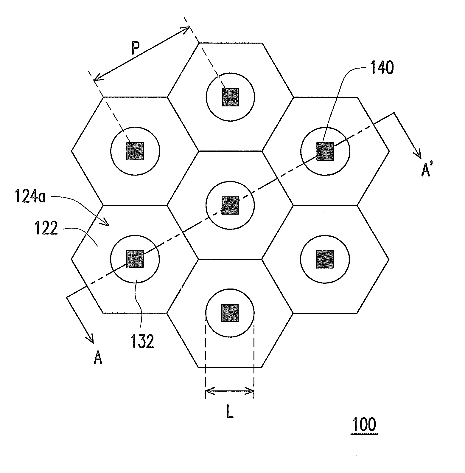
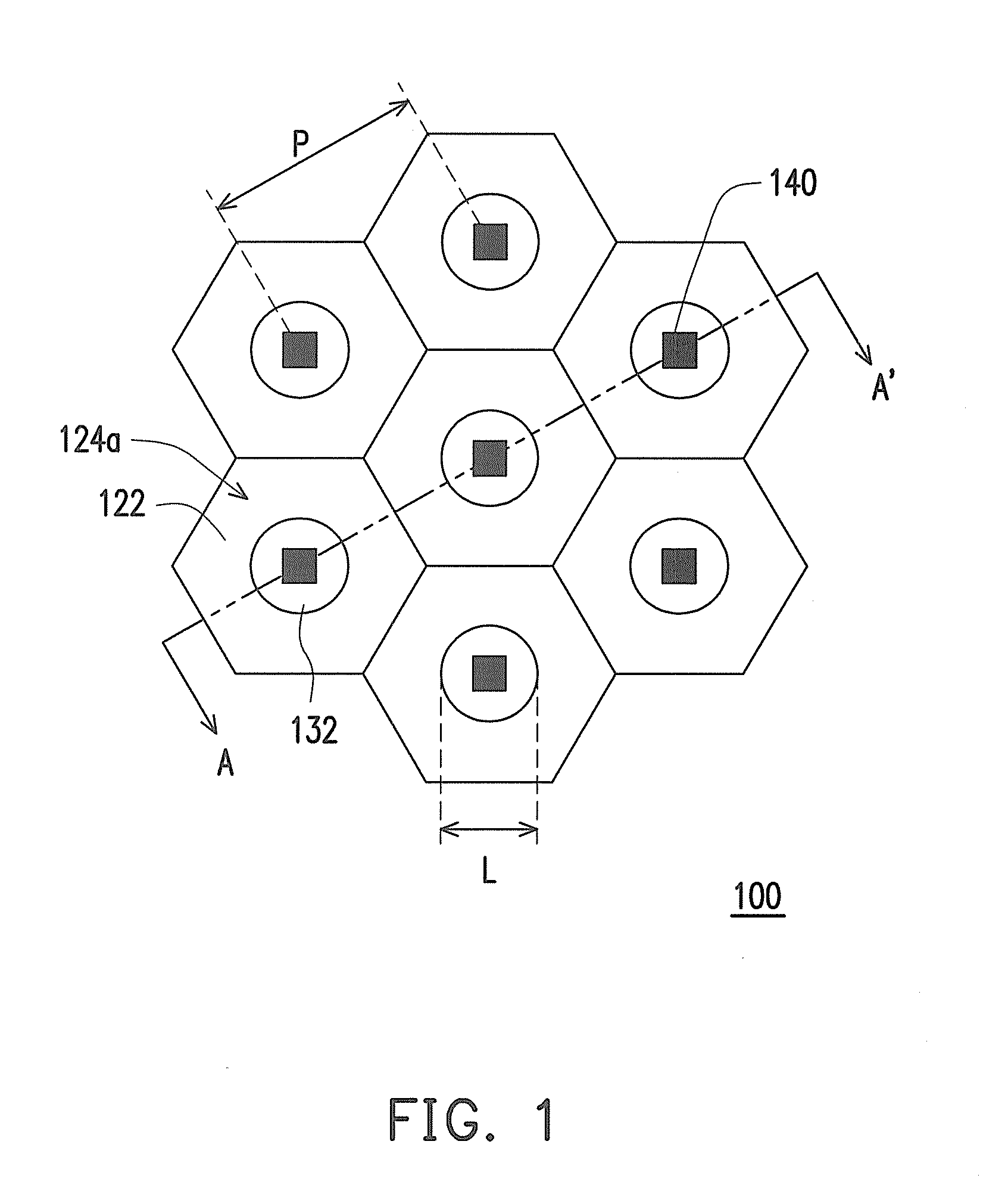
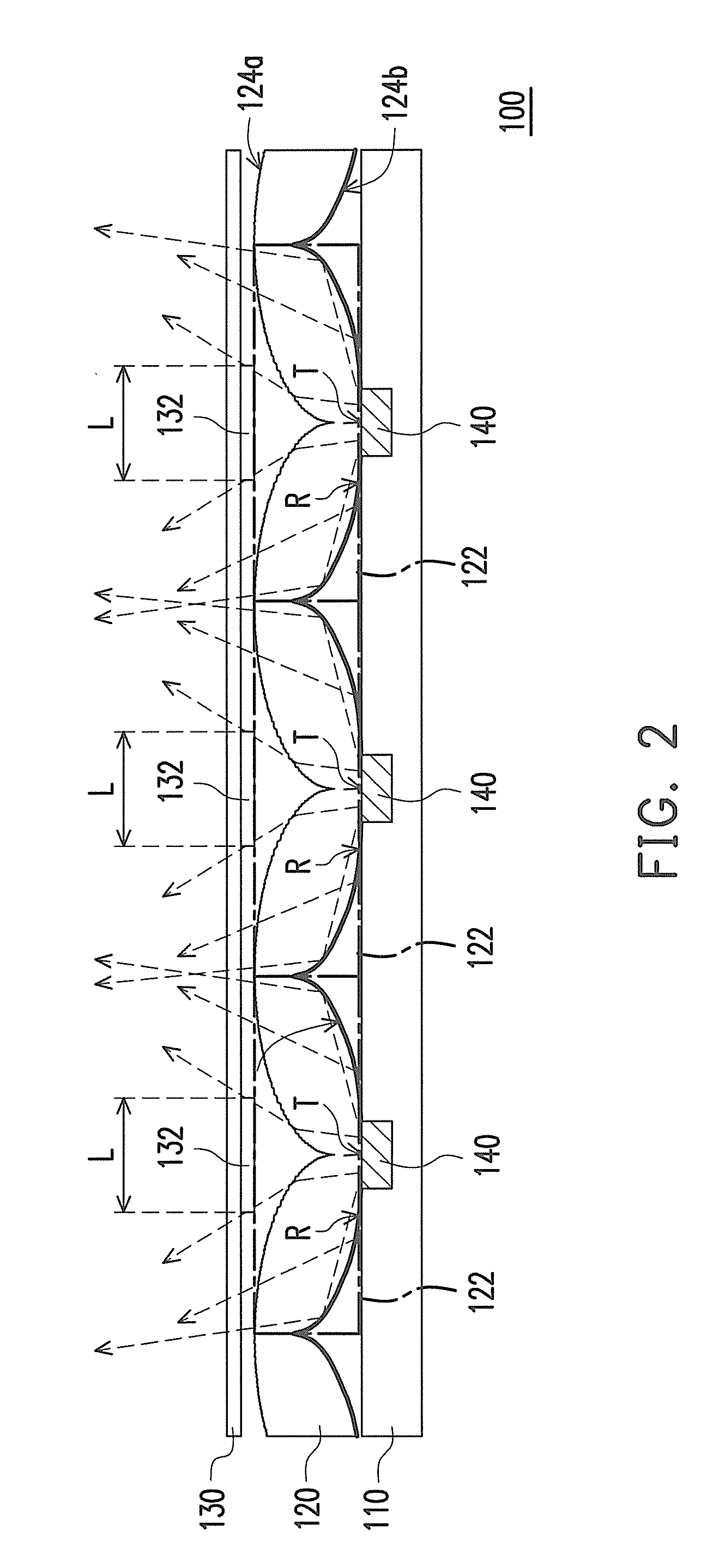
The invention is a flexible light source module that includes a flexible substrate, a flexible light guide film, and a plurality of point light sources. The flexible light guide film is disposed on the point light sources and includes a plurality of light-guiding portions. The light-guiding portions have a first light incident sub-surface closest to the geometric center and a first light emitting sub-surface opposite the light incident surface. The first light emitting sub-surface has ascending tangent slopes approaching the geometric center of the light-guiding portion. The flexible light source module provides a planar light source. The technical effect of the invention is a flexible and efficient light source that can be easily integrated into various applications.

Problems solved by technology

In reviewing the currently related technology, both the side-type light source module and the direct-type light source module have some shortages, for example, they have no flexibility.
On the other hand, the side-type light source module, due to the limitation of light-guiding distance, encounters difficulty on the application of a large area display; while the direct-type light source module, although it can be easily used in a large dimension display, but it is difficult to get diffusion uniforming, wherein a high density LED array or a certain optical path is required so as to achieve the effect of uniform planar light source.

Method used


Image

  • Flexible light source module
  • Flexible light source module
  • Flexible light source module

Examples


Embodiment Construction

[0020]Reference will now be made in detail to the preferred embodiments of the disclosure, examples of which are illustrated in the accompanying drawings. Wherever possible, the same reference numbers are used in the drawings and the description to refer to the same or like parts.

[0021]In the disclosed exemplary embodiment, a flexible light source module is, for example, a direct-type flexible planar light source module and includes a flexible light guide film with a corrugated light-guiding structure. By means of the corrugated light-guiding structure, the flexible light guide film is able to convert point light sources into a uniform planar light source. Meanwhile, the corrugated structure of the light guide film also enables the direct-type light source module having flexibility.

[0022]In the disclosed exemplary embodiment, the flexible light guide film includes, for example, a plurality of hexagon light-guiding portions. The light-guiding portions are periodically arranged, integ...


PUM


Abstract

A flexible light source module including a flexible substrate, a flexible light guide film and a plurality of point light sources is provided. The flexible light guide film including light-guiding portions is disposed on the point light sources. Each of the light-guiding portions includes a light incident surface and a light emitting surface. The light incident surface includes light incident sub-surfaces. The light emitting surface includes light emitting sub-surfaces, and the one closest to the geometric center of the light-guiding portion is a first light emitting sub-surface. The absolute values of the tangent slopes of the first light emitting sub-surface are ascending with approaching the geometric center of the light-guiding portion. The light beams emitted from the point light sources exit out of the flexible light source module via the flexible light guide film so that the flexible light source module provides a uniform planar light source.

Description

CROSS-REFERENCE TO RELATED APPLICATION[0001]This application claims the priority benefit of Taiwan application serial no. 99142586, filed on Dec. 7, 2010. The entirety of the above-mentioned patent application is hereby incorporated by reference herein and made a part of this specificationBACKGROUND[0002]1. Technical Field[0003]The disclosure generally relates to a light source module, and more particularly, to a flexible light source module.[0004]2. Description of Related Art[0005]Along with the progress of optoelectronic technology, the light-emitting diode (LED) light source has been applied in more broad fields, such as indicator box, illumination board, backlight module and advertising lamp board. Regardless of any applications, the LED light source has caused revolutionary impact on various illuminations and display products, which overthrows the mechanical impression as currently known. The most product applications for the LED light sources are towards developing a super-sli...

Claims


Application Information

Patent Timeline
Patent Type & Authority Applications(United States)
IPC IPC(8): F21V11/00
CPCF21V5/002F21Y2111/002H01L25/0753H01L33/58F21Y2101/02H01L2224/48091H01L2924/01322H01L2224/49107H01L2924/00F21Y2107/10F21Y2115/10H01L2924/00014
Inventor HUANG, CHEN-YANGTAI, TSAI-LINHSU, CHAO-KAI
Owner IND TECH RES INST
Learn More