
Intervertebral ligament having a helical bone fastener

a technology of intervertebral ligaments and fasteners, which is applied in the field of intervertebral ligaments having helical bone fasteners, can solve the problems of low profile of fixing systems, inability to further adjust the tension of ligaments, and limited design options

Active Publication Date: 2012-06-07
DEPUY SYNTHES PROD INC +1
View PDF1 Cites 2 Cited by
  • Summary
  • Abstract
  • Description
  • Claims
  • Application Information

AI Technical Summary

Benefits of technology

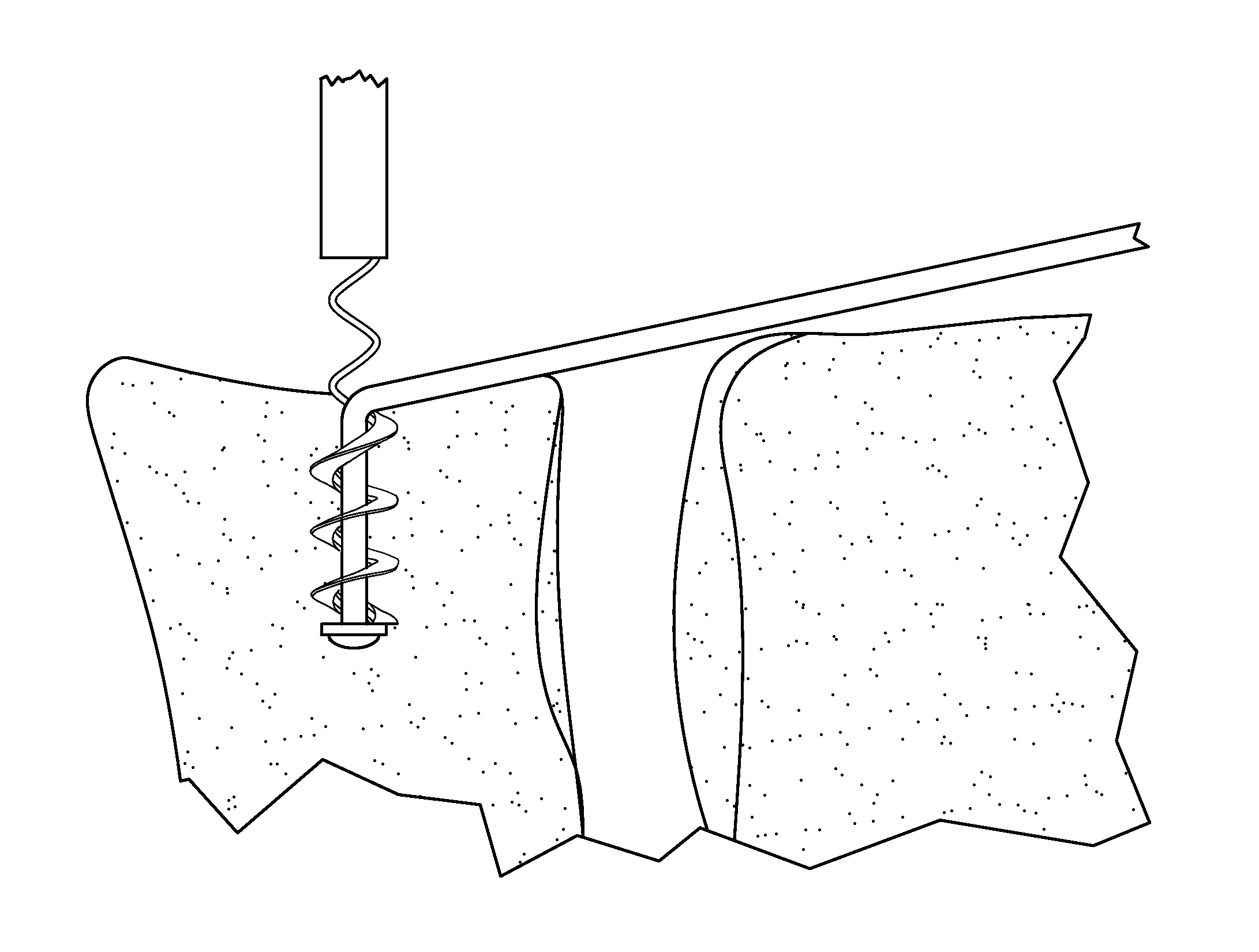
This solution provides a low-profile, bioresorbable intervertebral connection system that minimizes musculoskeletal removal, reduces impaction forces, and allows for in-situ tensioning of the ligament, enhancing the suitability and safety of spinal fusion procedures across various spinal areas.

Problems solved by technology

However, because anterior fixation, especially in the abdominal or thoracic area, lies in close proximity to vital internal organs such as the aorta, these fixation systems must also possess a low profile.
When the ligament is relatively rigid, it must essentially fully lie upon the anterior surfaces of the adjacent vertebrae, thereby limiting design options.
When the bone fastener is seated upon the vertebral surface, a portion of the bone fastener protrudes from the surface and the tension of the ligament can not be further adjusted.
These impaction forces may compromise the integrity of the bone fastener component.
This makes the implantation procedures very arduous, and, due to high impaction forces, may not be suitable for use in certain areas of the spine.

Method used


Image

  • Intervertebral ligament having a helical bone fastener
  • Intervertebral ligament having a helical bone fastener
  • Intervertebral ligament having a helical bone fastener

Examples


Embodiment Construction

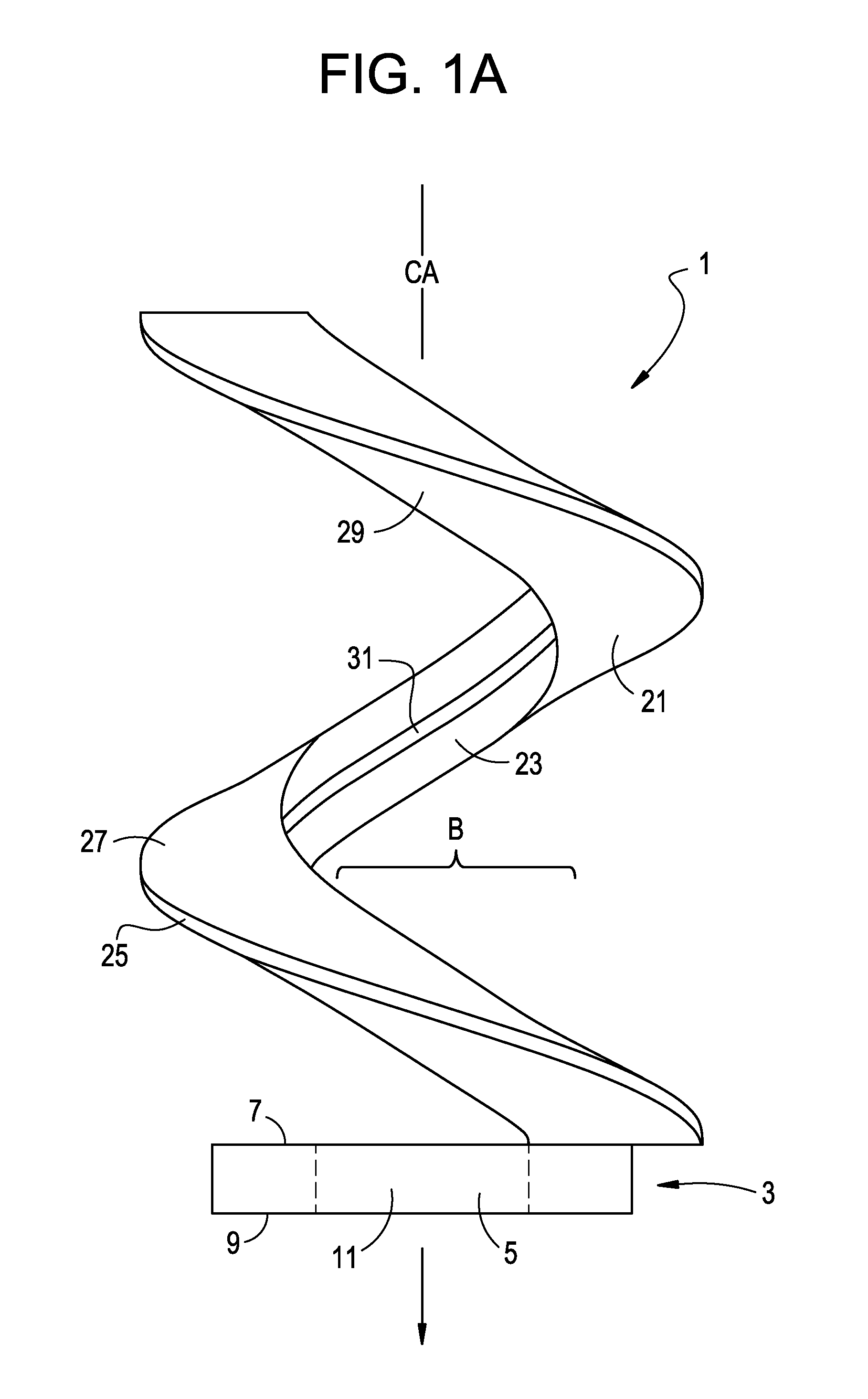
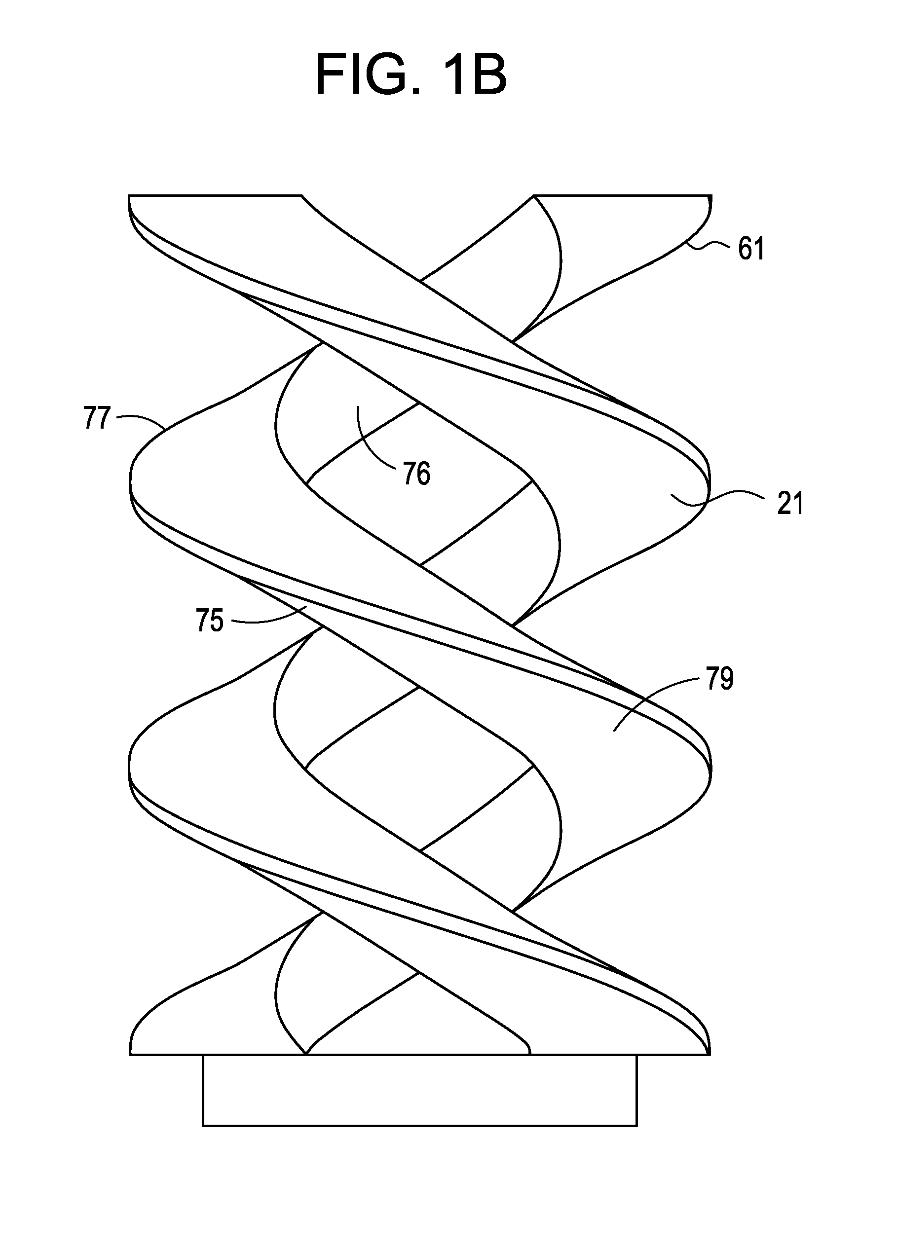
[0030]Referring now to FIG. 1a, there is provided an anchor having a central axis CA which is axially implantable into a bone in a patient's body, the anchor 1 comprising:[0031]a) a distal head portion 3 having a body portion 5 that extends transverse to the central axis of the anchor, a proximal surface 7, a distal surface 9, and an axially extending throughhole 11;[0032]b) a first helix 21 extending axially from the body portion of the distal head portion and transversely engagable with the bone, the first helix having an inner surface 23 defining a bore B, an outer surface 25, and upper 27 and lower 29 middle surfaces,

[0033]In this particular embodiment, the inner surface 23 of the first helix has a helical groove 31 that extends along the length of the helix. This helical groove defines a helical groove diameter.

[0034]In some embodiments, the distal head portion has a first diameter and the first helix has a second diameter, and the first diameter is no greater than the second d...


PUM


Abstract

An intervertebral connection system wherein the bone anchor has a helical configuration.

Description

CONTINUING DATA[0001]This divisional patent application claims priority from co-pending U.S. Ser. No. 11 / 139,961, filed May 27, 2005, entitled “Intervertebral Ligament having a Helical Bone Fastener”, the specification of which is incorporated by reference in its entirety.BACKGROUND OF THE INVENTION[0002]Single level spine fusion procedure typically entails removing the intervertebral disk (not shown) and inserting an interbody device into the disk space.[0003]Current spine fusion procedures rely heavily on the use of posterior fixation to achieve the stability and rigidity necessary to obtain successful clinical results. However, implantation of posterior instrumentation necessarily involves removing important musculoskeletal elements.[0004]Because of these concerns, anterior fixation systems have also been developed which require removal of much less musculoskeletal mass. However, because anterior fixation, especially in the abdominal or thoracic area, lies in close proximity to v...

Claims


Application Information

Patent Timeline
Patent Type & Authority Applications(United States)
IPC IPC(8): A61F2/08
CPCA61B17/7022A61B17/869A61B17/8875A61B17/8886A61B17/7082A61F2/44A61F2002/0864A61F2002/0888A61F2/0811A61F2/4611A61F2002/0841
Inventor PELLEGRINO, RICHARDRUSBARSKY, CHRISTINE
Owner DEPUY SYNTHES PROD INC
Learn More