
Locking Adjustment Dial Mechanism for Riflescope

Active Publication Date: 2012-06-14
LIGHTFORCE USA
View PDF2 Cites 4 Cited by
  • Summary
  • Abstract
  • Description
  • Claims
  • Application Information

AI Technical Summary

Benefits of technology

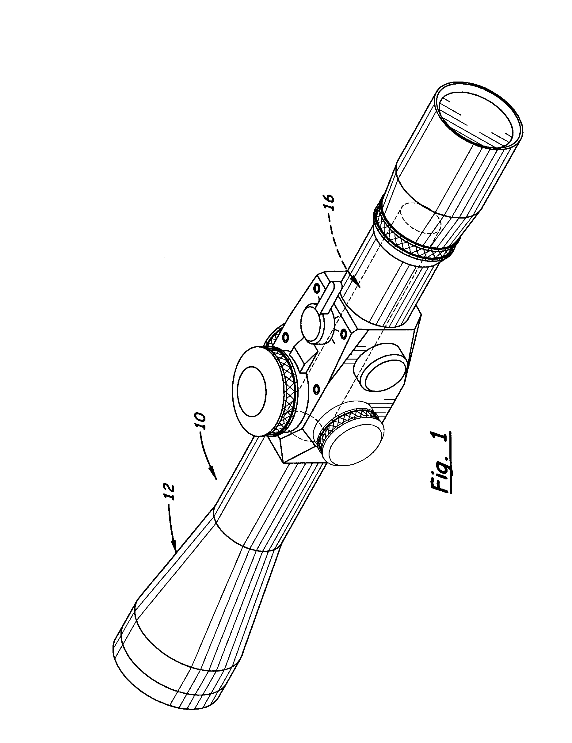
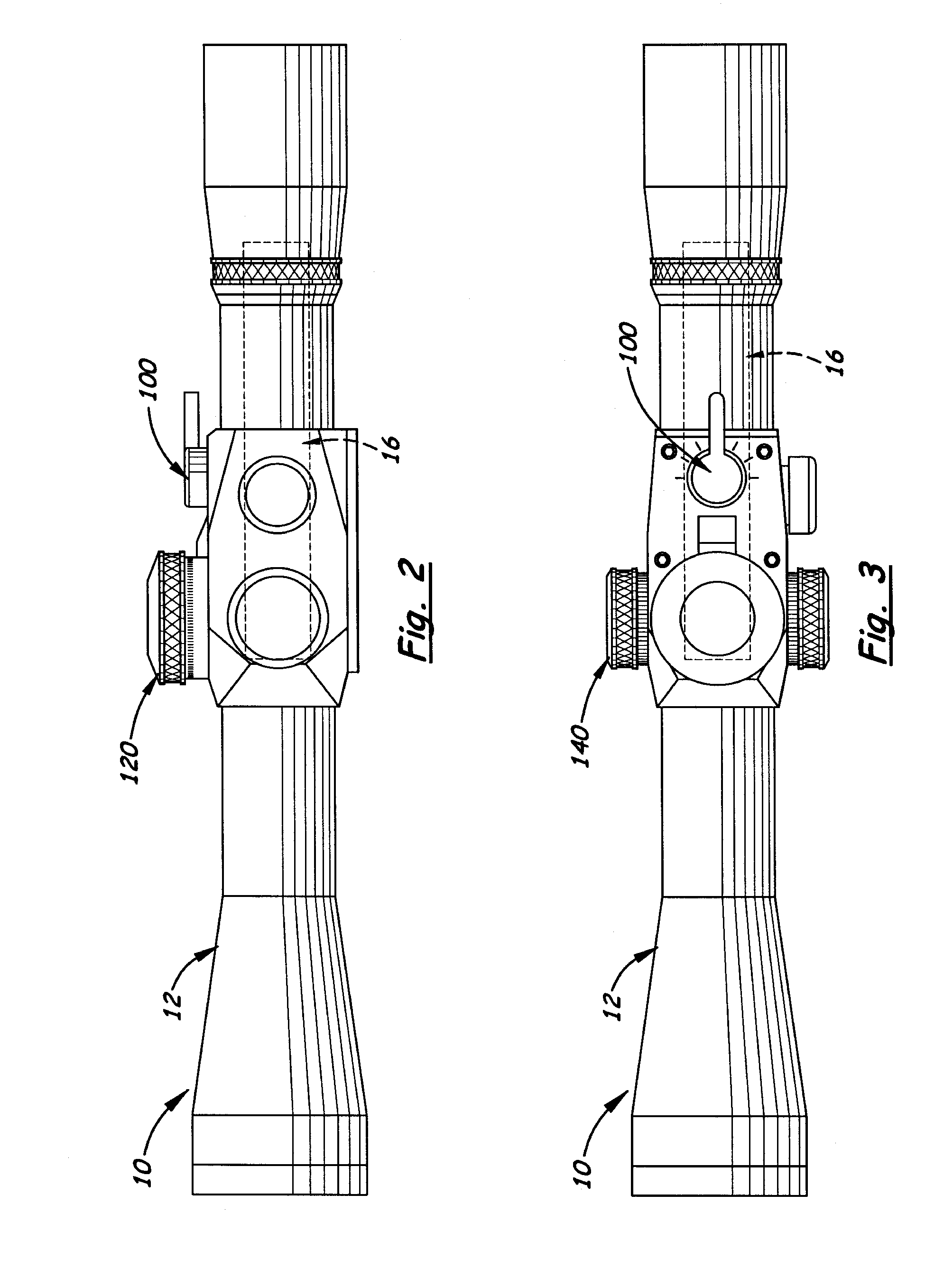
[0010]According to one embodiment, stop tabs are mounted on the side of the coarse adjustment dial and the windage dial, which are engaged by locking arms mounted on the scope body. During use, the tabs and release arms are used to create a zero point for the riflescope. When pressed, the locking arms disengage from the stop tabs and allows the coarse elevation dial and the windage dial to rotate freely in either direction beyond the pre-defined zero point. When the coarse elevation dial or the windage dial are rotated back to their original location, the locking arms re-engage the stop tabs automatically resetting the original zero point, locking both elevation and windage turrets, thus preventing accidental change to the shooters original zero point.

Problems solved by technology

This can create a slow and confusing situation for the shooter because the dial position must be counted and does not reflect the actual scope adjustment setting, thereby slowing engagement time with the target.
If the elevation adjustment has relatively small MOA (or milliradian) click values, the total amount of elevation movement per rotation of the adjustment, is limited.
Once set, this type of stop feature does not allow the adjustment dial to be rotated beyond the preselected “zero” point to a “negative” range.
These lock at every selected adjustment position and do not provide a mechanical stop or non-visual indication when the adjustment dial reaches the “zero” position.

Method used


Image

  • Locking Adjustment Dial Mechanism for Riflescope
  • Locking Adjustment Dial Mechanism for Riflescope
  • Locking Adjustment Dial Mechanism for Riflescope

Examples


first embodiment

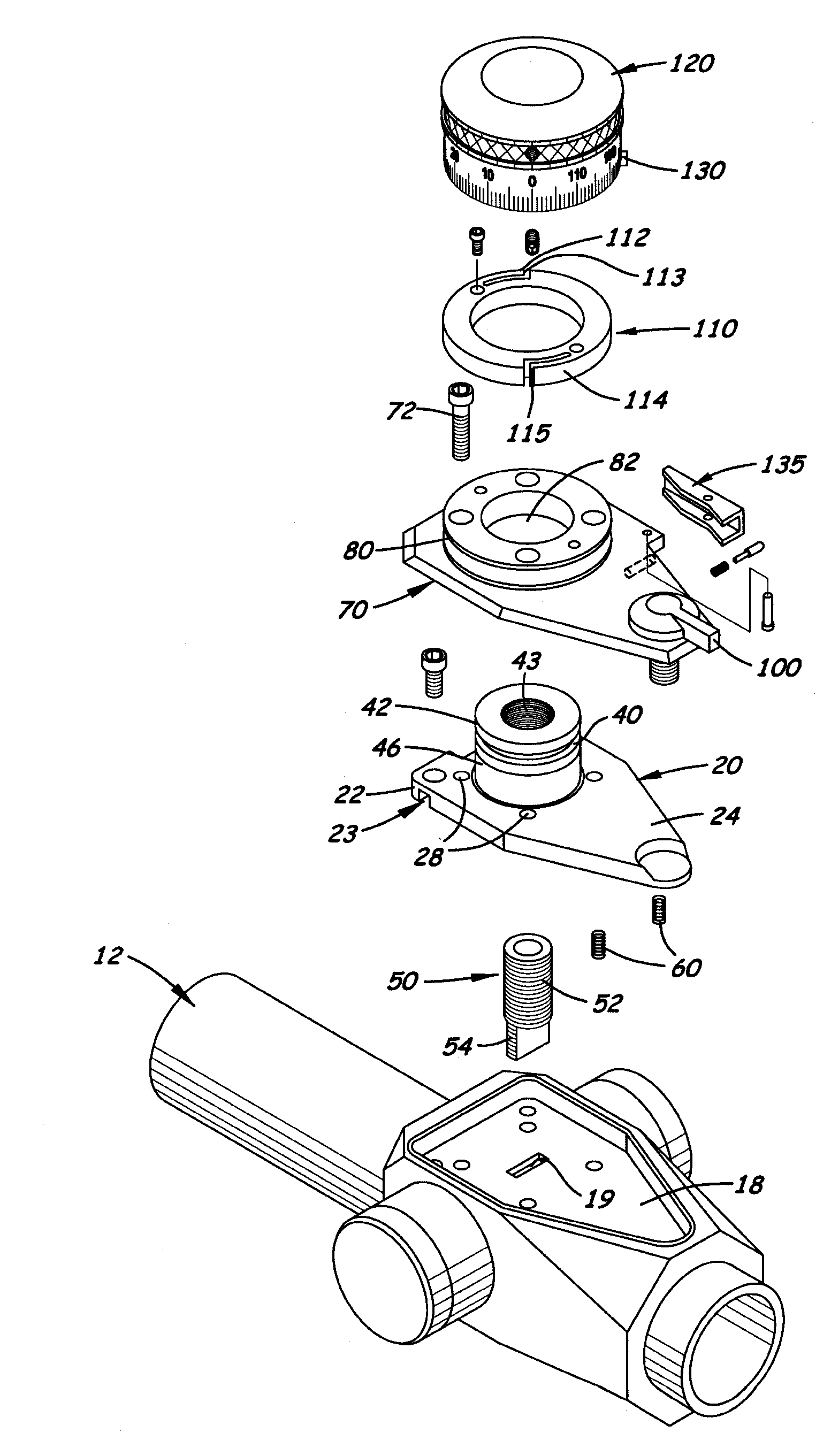
[0030]In the first embodiment, shown in FIGS. 4-6, the adjustment plate is a flex plate 20 affixed along its front edge to the mounting surface 18. The flex plate 20 includes a flat plate 21 with a transversely aligned groove 23 formed on its lower surface. The groove 23 enables the rear section of the flex plate 20 to bend upward when an upward force is exerted on the rear section 24 of the flex plate 20. The flex plate 20 is slightly beveled so that when the front section 22 of the flex plate 20 is attached to the mounting surface 18, the rear section 24 is slightly elevated above the mounting surface 18. One or more optional springs 60 are disposed between the rear section 24 and the mounting surface 18 to bias the rear section 24 upward.

[0031]The rotating post member 40 includes a top jam nut 42, an upper bearing support 44 and a lower bearing support 48. Located between the upper bearing support 44 and the top surface of the flex plate 20 is an upper bearing 46A. Located betwee...

second embodiment

[0032]In a second embodiment, shown in FIGS. 7-9, the flex plate 20 is replaced with a hinge plate 20′. The hinge plate 20′ is affixed along its front section to a transversely aligned hinge pin 22′ attaching it to the hinge joint 25′ located in front of the hinge plate 20′. The hinge joint 25′ is securely attached to the cover plate 70 located above the hinge plate 20′ with two screws 29′ allowing the hinge plate 20′ to “float” in the mounting surface 18 after assembly. In the preferred embodiment, the hinge plate 20′ has a flat thick front section and a thinner rear section 26′ allowing the mounting of the cam follower ball 28. When the front section of the hinge plate 20′ is pinned to the hinge joint 25′ and attached to the cover plate 70, the cam follower ball 28 rests against cam face 108 discussed further below.

[0033]One or more optional springs 60′ are disposed between the rear section of the hinge plate 20′ and the mounting surface. 18. The springs 60′ bias and help hold the...


PUM


Abstract

Described is a locking stop mechanism for a riflescope that includes at least one rotatable reticle adjustment dial mounted on a scope body. It includes a stop member on the adjustment dial at a preselected position and a lock member on the scope body. The lock member is positioned to engage the stop member upon rotation of the adjustment dial to a preselected setting. The lock member is configured to prevent rotation of the adjustment dial in either direction when engaged with the stop member while allowing free rotation in at least one direction when the lock member is manually displaced and when the stop member is not engaged with the lock member at the preselected setting.

Description

BACKGROUND[0001]This application is a continuation-in-part of my co-pending U.S. patent application Ser. No. 12 / 363,658, titled Riflescope High Speed Adjusting Elevation Assembly, filed Jan. 30, 2009 and claiming priority to U.S. provisional patent application Ser. No. 61 / 063,265, filed on Jan. 31, 2008, and Ser. No. 61 / 144,400, filed on Jan. 13, 2009.[0002]1. Technical Field[0003]This invention pertains to riflescopes and more particularly to riflescopes with elevation and / or windage adjustment knobs that can be releasably locked at a preselected “zero” position.[0004]2. Description of the Related Art[0005]Riflescopes typically include elevation adjustments that enable the shooter to shoot accurately at different target distances by turning the elevation adjustment mounted on the top of the riflescope. When the elevation adjustment is rotated, the riflescope's elevation changes from the scope's zero point. Conventional elevation adjustments on a riflescope have preset “click” value...

Claims


Application Information

Patent Timeline
IPC IPC(8): F41G1/38
CPCF41G1/38
Inventor HUBER, JEFF
Owner LIGHTFORCE USA
Learn More