Slide rail device for vehicle seat

a technology for sliding rails and vehicle seats, which is applied in the direction of moving seats, machine supports, other domestic objects, etc., can solve the problems of unstable sliding operation of the upper rail and the lower rail, and the rollability of the balls can be deteriorated, and achieve the effect of high dimensional accuracy and hardness, and affecting the rollability of balls

Inactive Publication Date: 2012-06-14
SHIROKI KOGYO CO LTD
View PDF7 Cites 3 Cited by
  • Summary
  • Abstract
  • Description
  • Claims
  • Application Information

AI Technical Summary

Benefits of technology

[0006]As a result of having pursued the cause of the lack of stability of the sliding operation of the slide rail device, the inventor of the present invention has completed the present invention after coming to the conclusion that if the radius of the balls is made to be identical to the radius of curvature of the ball contact portion of each rail, there is a possibility of a combination of a ball and a rail being unintentionally produced in which the radius of curvature of the ball contact portion of the rail is smaller than the radius of the balls due to manufacturing error, thus causing the ball and the rail to be in contact with each other at two points to thereby deteriorate the rollability of the balls. The balls (steel balls) are extremely high in dimensional accuracy and hardness, as is known in the art, so that there is little possibility of an error in the dimensional accuracy of the balls affecting the rollability thereof. The length (angle) of the circular arc in each ball contact R-portion of the lower rail is usually greater than that of the upper rail, so that the shapes of the ball contact R-portions of the lower rail greatly affect the rollability of the balls.
[0015]By setting the outward crossing angle in this manner, the pair of upper-rail side walls can be securely made to be resiliently deformable inwardly (i.e., in directions toward each other) via the lower balls. It has been confirmed that deformation of the pair of upper-rail side walls outwardly in opposite directions away from each other may deteriorate the slidability of the slide rail device.
[0017]According to the present invention, the radius of curvature of each ball contact R-portion of at least the lower rail is set to be greater than the radius of the associated balls, which makes it possible to obtain a slide rail device in which the indentation prevention performance and the rollability of the ball are well-balanced.

Problems solved by technology

However, the inventor of the present invention has found that, if the radius of the balls is made to be identical in design to the radius of curvature of the ball contact portions of each rail, the rollability of the balls sometimes deteriorates regardless of the presence or absence of indentations on the rails (aside from the problem of indentations), to thereby make the sliding operation of the upper rail with respect to the lower rail unstable.

Method used


Image

  • Slide rail device for vehicle seat
  • Slide rail device for vehicle seat
  • Slide rail device for vehicle seat

Examples


Embodiment Construction

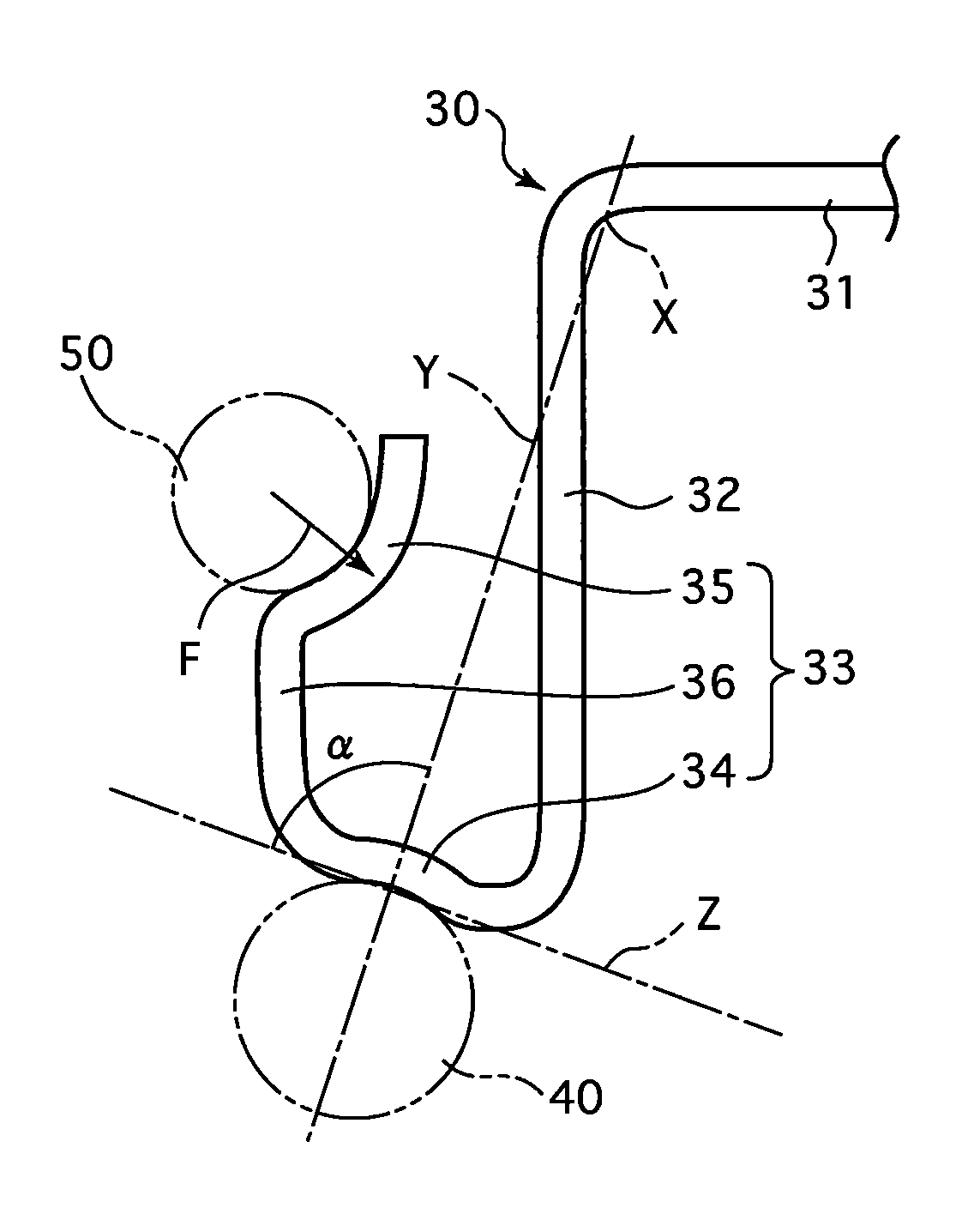
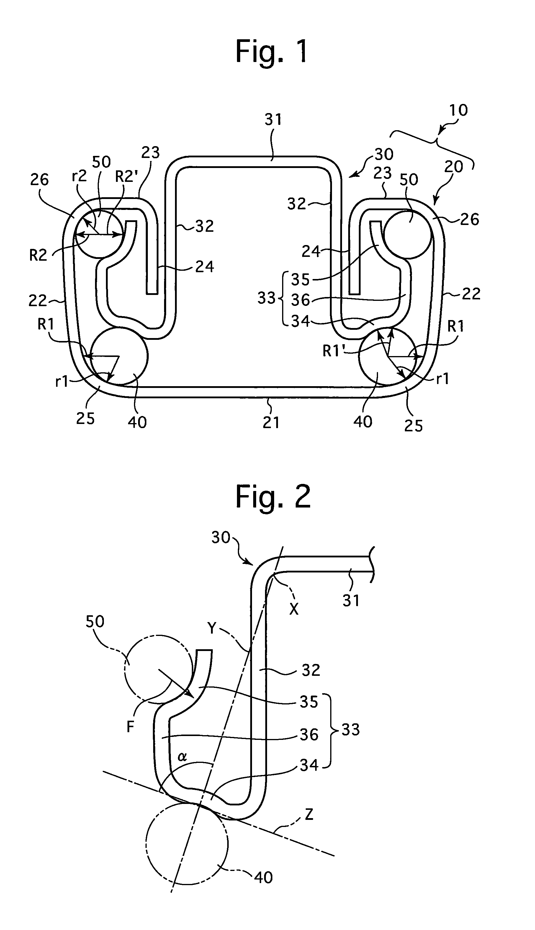
[0025]FIG. 1 shows an embodiment of a slide rail device 10 according to the present invention. The slide rail device 10 is provided with a lower rail 20 and an upper rail 30 which are fixed to a vehicle floor (not shown) and a vehicle seat (not shown), respectively, and is provided between the lower rail 20 and the upper rail 30 that are engaged with each other to be relatively slidable, with two types of steel balls, i.e., lower balls 40 and upper balls 50, which are installed between the lower rail 20 and the upper rail 30. The slide rail device 10 is bilaterally symmetrical in shape in a cross section taken along a plane normal to the extension direction (lengthwise direction) of the rails 20 and 30. The lower balls 40 are greater in diameter than the upper balls 50. As known in the art, two of the slide rail devices 10 are used as a pair (left and right slide rail devices) in a state of being fixed to a vehicle, and a lock mechanism and other components are installed to this pai...


PUM


Abstract

A slide rail device which includes a lower rail, an upper rail which is freely slidably engaged with the lower rail, and balls which are installed between the lower and upper rails. The lower rail includes a lower-rail bottom wall, a pair of lower-rail side walls, a pair of lower-rail upper walls, a pair of lower-rail lower-ball contact R-portions, and a pair of lower-rail upper-ball contact R-portions. The upper rail includes an upper-rail top wall, a pair of upper-rail side walls, and a pair of upper-rail ball-bearing walls. Each upper-rail ball-bearing wall includes an upper-rail lower-ball contact portion and an upper-rail upper-ball contact portion. A radius of curvature of the lower-rail lower-ball contact R-portion of the lower rail is greater than that of the lower ball, and a radius of curvature of the lower-rail upper-ball contact R-portion of the lower rail is greater than that of the upper ball.

Description

BACKGROUND OF THE INVENTION[0001]1. Field of the Invention[0002]The present invention relates to a slide rail device for making an adjustment to the position of a vehicle seat in the forward / rearward direction.[0003]2. Description of Related Art[0004]A typical slide rail device (slide rail assembly) is configured of a lower rail that is fixed to a vehicle floor, an upper rail that is fixed to a vehicle seat and engaged with the lower rail to be freely slidable thereon, and balls (steel balls) for reducing frictional resistance that are installed between the upper rail and the lower rail. The upper rail and the lower rail are each made of a metallic material (usually an iron-based material) having a uniform cross section. Such a slide rail device is disclosed in Japanese Patent Publication No. 4,230,945.[0005]In this known slide rail device, application of a force on the upper rail and the lower rail therebetween that is produced by the weight of someone (a driver or a passenger) sit...

Claims


Application Information

Patent Timeline
Patent Type & Authority Applications(United States)
IPC IPC(8): B60N2/07
CPCB60N2/0705B60N2/072F16C29/048B60N2/0722
Inventor KIMURA, AKIHIRO
Owner SHIROKI KOGYO CO LTD
Why Eureka
Try Eureka