
Vehicle body moving cart

a technology for moving carts and vehicles, applied in the field can solve the problems of increasing investment costs, difficulty in applying the aforementioned conventional vehicle body moving carts to vehicle bodies associated, and increasing the structure of vehicle body moving carts, so as to simplify the overall system configuration and reduce the initial investment cost

Active Publication Date: 2012-06-14
HYUNDAI MOTOR CO LTD +1
View PDF1 Cites 33 Cited by
  • Summary
  • Abstract
  • Description
  • Claims
  • Application Information

AI Technical Summary

Benefits of technology

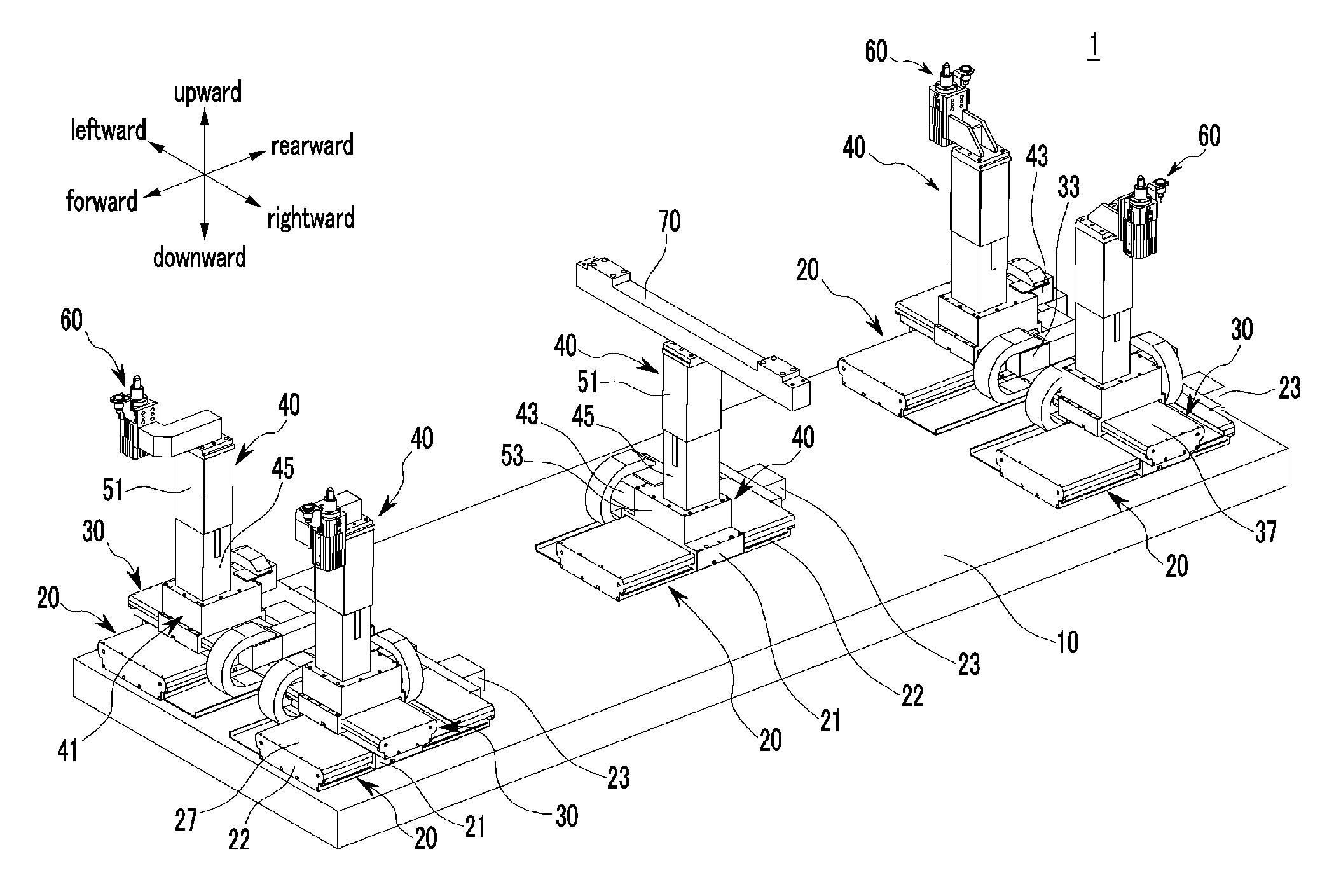
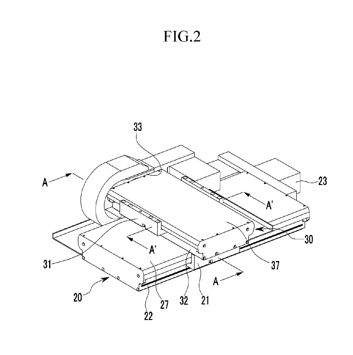
The present invention provides a vehicle body moving cart that can be used with different types of vehicles by configuring the pin clampers and the support frame to be freely movable in position on the base frame. The cart includes first and second moving units that can move the vehicle body in different directions. The first moving unit has a first sliding plate and a first drive motor, while the second moving unit has a second sliding plate and a second drive motor. The cart also includes an ascending and descending unit with a gear box, ascending and descending blocks, and an ascending and descending case. The cart can be used with various vehicle body shapes and sizes, reducing initial investment costs and simplifying the overall system configuration.

Problems solved by technology

However, it is difficult to apply the aforementioned conventional vehicle body moving cart commonly to vehicle bodies associated with different vehicle types as the vehicle bodies come in different shapes and sizes according to vehicle type.
Moreover, the manufacture of dedicated vehicle body moving carts according to vehicle type incur large investment costs that increase each time a new vehicle model or type is introduced because of the additional costs associated with remodeling and creating a new vehicle body moving cart.
Even further, as vehicle models or types advance the structure of the vehicle body moving carts will also become more and more complicated.

Method used


Image

  • Vehicle body moving cart
  • Vehicle body moving cart
  • Vehicle body moving cart

Examples


Embodiment Construction

[0060]An exemplary embodiment of the present invention will hereinafter be described in detail with reference to the accompanying drawings.

[0061]The embodiment described in the present specification and the configuration shown in the drawings are merely an exemplary embodiment of the present invention and do not represent all of the technical spirit of the present invention. Thus, it should be understood that there may be various equivalents and modified examples that can replace the embodiments described in the present specification and the configuration shown in the drawings at the time of filling the present application.

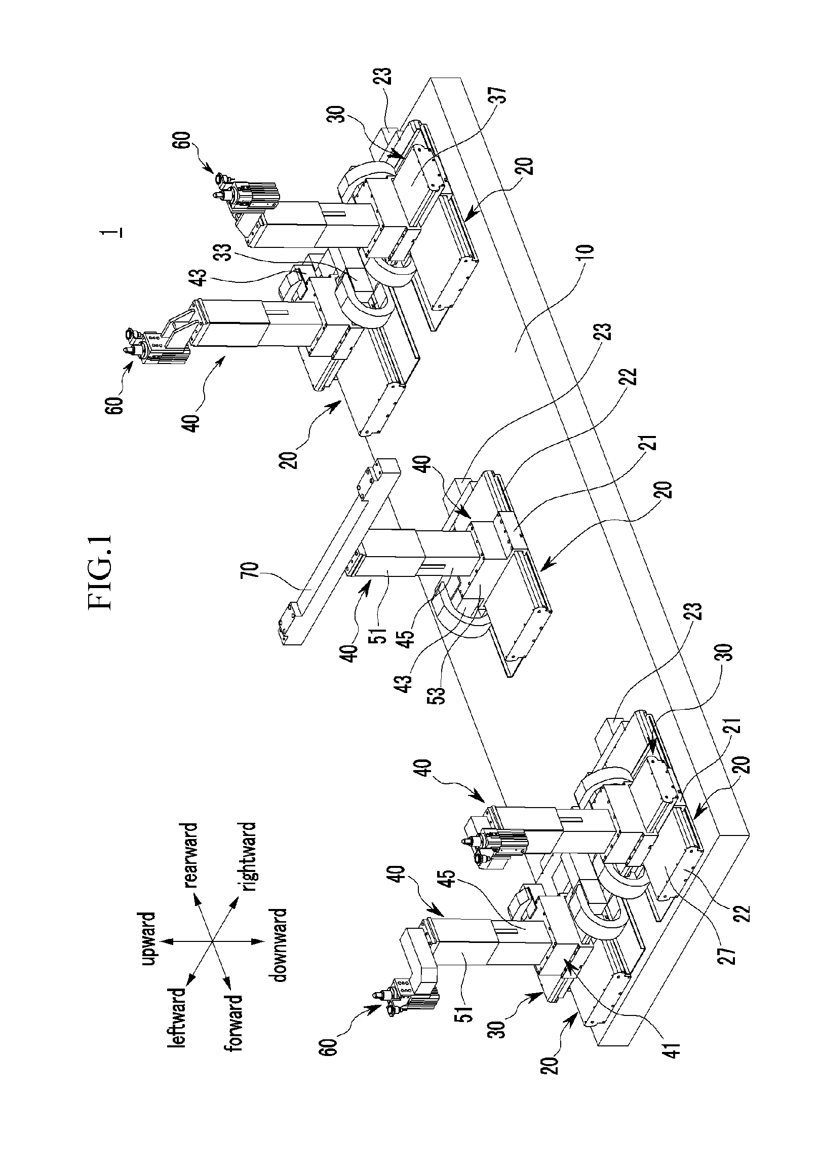
[0062]FIG. 1 is a perspective view of a vehicle body moving cart according to an exemplary embodiment of the present invention. FIG. 2 is a perspective view of first and second moving units applied to the vehicle body moving cart according to exemplary embodiment of the present invention. FIG. 3 is a cross-sectional view taken along line A-A and line A′-A′ of FIG....


PUM

PropertyMeasurementUnit
torqueaaaaaaaaaa
shapesaaaaaaaaaa
sizesaaaaaaaaaa

Abstract

A vehicle body moving cart is provided which includes a base frame and first moving units that are installed at the front, rear and center of the base frame, respectively. The first moving units are configured to reciprocate first sliding plates forward and rearward on the base frame, respectively. In addition to the first moving units, second moving units are disposed perpendicular to the first moving units installed at the front and rear of the base frame, respectively, and installed on the first sliding plates to move the second sliding plates leftward and rightward on the base frame, respectively. Installed on the second sliding plates and the first sliding plate of first unit installed at the center of the base frame, are ascending and descending units. These ascending and descending units are configured to be reciprocally movable upward and downward on the base frame.

Description

CROSS-REFERENCE TO RELATED APPLICATION[0001]This application claims priority to and the benefit of Korean Patent Application No. 10-2010-0124904 filed in the Korean Intellectual Property Office on Dec. 8, 2010, the entire contents of which are incorporated herein by reference.BACKGROUND OF THE INVENTION[0002](a) Field of the Invention[0003]The present invention relates to a vehicle body moving cart, and more particularly to a vehicle body moving cart, which is configured to correspond to vehicle bodies of different shapes and sizes and commonly applicable to various types of vehicles.[0004](b) Description of the Related Art[0005]Generally, vehicles are manufactured via numerous assembling processes using about twenty to thirty thousands of parts. In particular, vehicle bodies are formed by a first assembling process to produce vehicle body panels in a press process, and each part of the vehicle body is then assembled in a vehicle body factory to form a vehicle body of a body-in-whit...

Claims


Application Information

Patent Timeline
Patent Type & Authority Applications(United States)
IPC IPC(8): B23Q3/18
CPCB62D65/026Y10T29/49829B62D65/18
Inventor KIM, DONG MYONG
Owner HYUNDAI MOTOR CO LTD
Learn More