Noncontact charger system

a charger system and charger technology, applied in the direction of electrochemical generators, instruments, transportation and packaging, etc., can solve the problems of increasing the manufacturing cost of the noncontact charger system, high cost of the control unit such as the microcomputer that performs the process in accordance with a control program stored in advance,

Inactive Publication Date: 2012-06-14
PANASONIC INTELLECTUAL PROPERTY MANAGEMENT CO LTD
View PDF12 Cites 175 Cited by
  • Summary
  • Abstract
  • Description
  • Claims
  • Application Information

AI Technical Summary

Benefits of technology

[0014]An object of the present invention is to provide a noncontact charger system capable of realizing the detection at low-cost that in a state in which a power transmit

Problems solved by technology

However, generally, a control unit such as a microcomputer that performs processes in accordance with a control program stored in advance is expensive.
Therefore, since a control unit of th

Method used


Image

  • Noncontact charger system
  • Noncontact charger system
  • Noncontact charger system

Examples


Embodiment Construction

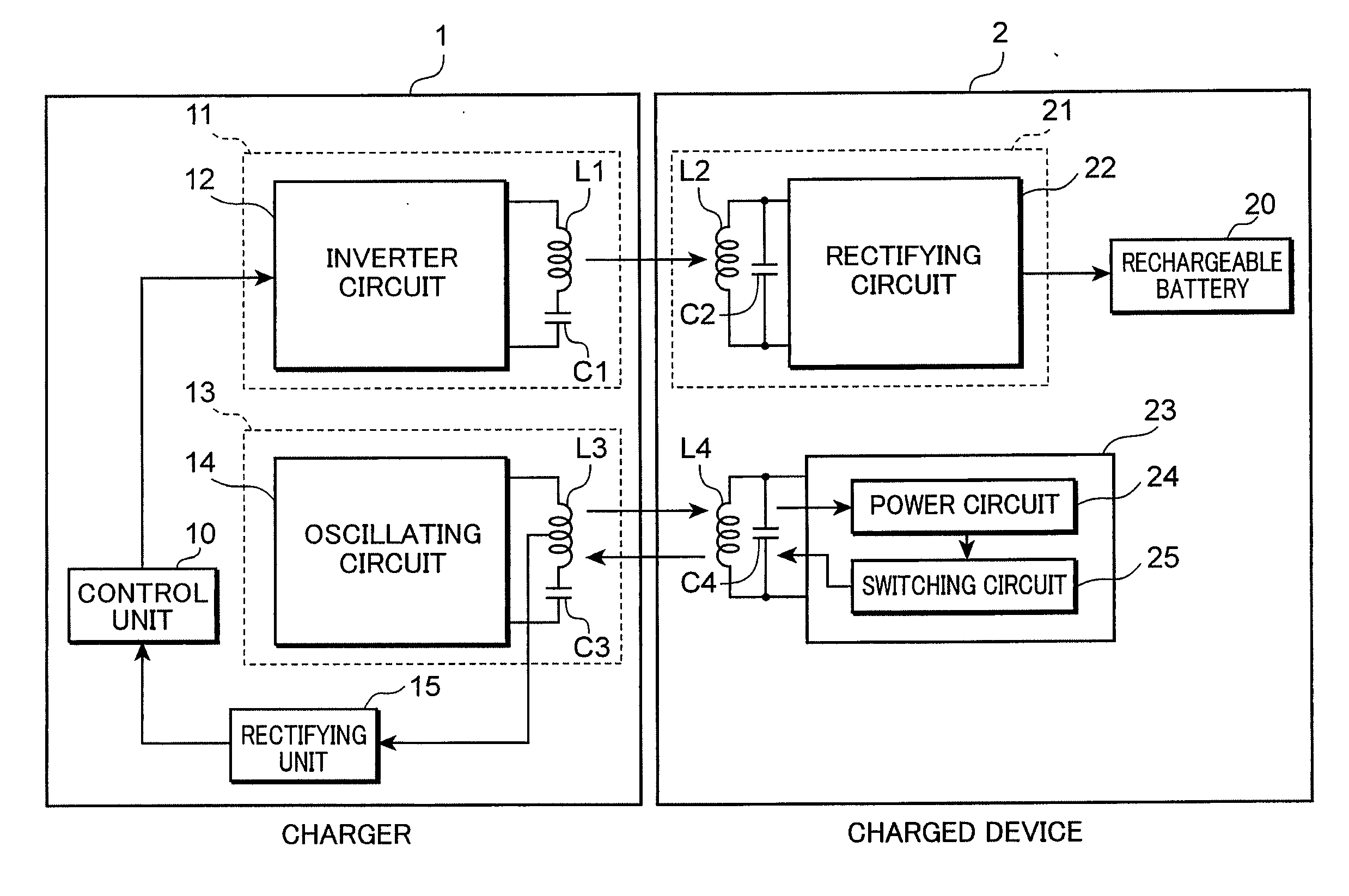
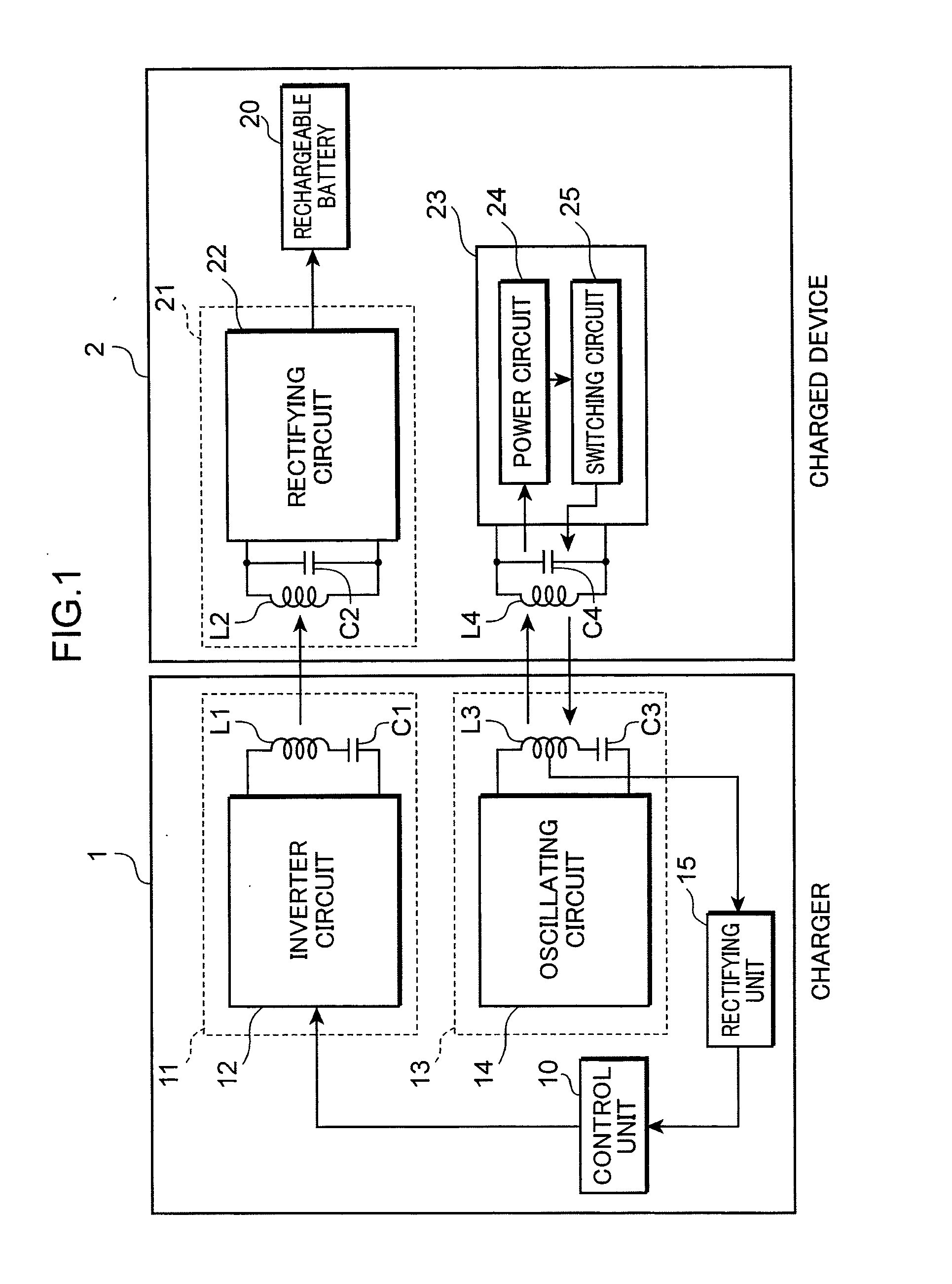
[0037]In a noncontact charger system, it is conceivable to use a set of coils for power transmission for an original purpose of transmitting power from a power transmitting side to a power receiving side and, in addition, to respectively provide authenticating system coils on the power transmitting side and the power receiving side. An authenticating system coil is a coil used to determine whether or not a combination of a power transmitting side and a power receiving side is legitimate and to determine whether or not a foreign object is present between the power transmitting side and the power receiving side. However, in this case, the following problem may occur.

[0038]For example, when a combination of a power transmitting side and a power receiving side is legitimate, there may be a case in which a foreign object is present within a predetermined gap formed by respective power transmitting system coils of the power transmitting side and the power receiving side but the foreign ob...


PUM


Abstract

A noncontact charger includes a charger having a power transmitting planar coil that transmits high-frequency charging power and a charged device including a power receiving planar coil magnetically coupled to the power transmitting planar coil to receive the charging power, wherein the charger includes a primary authentication planar coil which transmits high-frequency authenticating power for authenticating the charged device and receives a high-frequency authenticating signal for authenticating the charged device, a secondary authentication planar coil is magnetically coupled to the primary authentication planar coil to receive the authenticating power and output the authenticating signal generated from the authenticating power to the primary authentication planar coil, and a space between the power transmitting planar coil and the power receiving planar coil overlaps with a space between the primary authentication planar coil and the secondary authentication planar coil.

Description

TECHNICAL FIELD[0001]The present invention relates to a noncontact charger system.BACKGROUND ART[0002]Conventionally, there are noncontact charger systems which charge a charged device such as an electric shaver or an electric toothbrush when the charged device is set to a charger by transmitting power with a predetermined high frequency to the charged device.[0003]An example of a noncontact charger system is described in Patent Document 1. Patent Document 1 describes a power transmitting coil and a power receiving coil provided so as to oppose each other, wherein power is transmitted from the power transmitting coil to the power receiving coil due to mutual induction occurring between the power transmitting coil and the power receiving coil.[0004]In addition, recently, power transmitting coils and power receiving coils are sometimes constituted by planar coils in order to reduce installation space of the coils. Patent Document 2 describes an example of a noncontact charger system u...

Claims


Application Information

Patent Timeline
IPC IPC(8): H02J7/00H01F38/14
CPCH01F38/14H02J2007/0001G01V3/102H01M10/46H02J7/025H02J7/00045H02J50/10Y02E60/10H02J50/60H02J50/12H02J50/80
Inventor KITAMURA, HIROYASU
Owner PANASONIC INTELLECTUAL PROPERTY MANAGEMENT CO LTD
Why Eureka
Try Eureka